Over the years we’ve seen quite a few projects involving vector graphics, but the spaceship game created by [Mark Aren] especially caught our eye because in it he has tackled building a vector display from scratch rather than simply using a ready-made one such as an oscilloscope. As if the vector game itself wasn’t interesting enough, the process of designing the electronics required to drive a CRT is something that might have been commonplace decades ago but which few electronics enthusiasts in 2020 will have seen.
In his write-up he goes into detail on the path that took him to his component choices, and given the unusual nature of the design for 2020 it;s a fascinating opportunity to see the job done with components that would have been unheard of in the 1950s or 1960s. He eventually settled on a high voltage long-tailed pair of bipolar transistors, driven by a single op-amp to provide the differential signal required by the deflection electrodes. The mix of old and new also required a custom-fabricated socket for the CRT. On the game side meanwhile, an ATmega328 does the heavy lifting, through a DAC. He goes into some detail on DAC selection, having found some chips gave significant distortion.
All in all this is an impressive project from all angles, and we’re bowled over by it. Of course, if you fancy a play with vector graphics, perhaps there’s a simpler way.


Oh – I thought you were saying he made the CRT as well.
Aye. I read it the same way, and wanted to see his glass-blowing/vacuum-sealing/phosphor-coating setup! After looking at his actual project page, I could see that the CRT was actually built by AEG. Still a delightful project, and the body text of this article is fine, but I think that the title: “Building a Vector Graphics Machine From Scratch Including the CRT” is misleading.
But not impossible to build a CRT from scratch. If someone can make nixie tubes, monochrome CRT wouldn’t be impossible. Color CRT now that’s going to be very challenging.
Color CRTs aren’t that much more complicated than monochrome. Difficult to make perfectly, but not difficult to make. Once you can make three guns (hint: make one gun, then make two more just like it), and can make a shadow mask (hint: photoresist and chem etching), you’ve done all of the hard part. Getting that first gun to work is much harder.
CRT monitors suck why not use an lcd display?
@William Perez: Why CRTs instead of LCDs? Because at their very best, LCDs are still pixel-based devices. CRTs are inherently analog, and you can make a straight line in any direction without getting any form of stair-step artifacts. And yes, CRTs DO suck.
That CRT faceplate doesn’t look thick enough to have integral implosion protection. It would be prudent to slap a piece of polycarbonate sheet in front of it for this purpose. Way to easy to accidentally scratch the glass, leading to a crack, leading to an implosion.
What are the consequences of such accident? I am too young to remember this issue :-)
Well, think about having chunks of razor-sharp glass flying around the room at something approaching the speed of sound. That’s probably a worst-case-scenario (sometimes they just go “pop!” and collapse inward), but it can happen.
Source: As a kid I smashed quite a number of CRTs for my Dad for his TV repair business. The trash collectors wouldn’t take them if they were intact. Things were a bit different 40 years ago…
It doesn’t have that much energy to send it flying, but it does do a number on your eyes and face to be looking in the same direction when it happens.
With a CRT this small, not much, there is just not much volume to get things moving. Not much worse than a light bulb or fluorescent lamp.
It was standard practice on 5″ oscilloscopes (and this is a 5″ tube) to use implosion protection. Look at any Tektronix 5″ scope.
When the glass breaks on a large vacuum tube, the fragments are sucked in violently enough that they collide with each other and spray outward. This can be a problem if the vacuum tube is a CRT, with someone’s eyes facing it. CRT TVs had either a separate piece of laminated glass in front of the CRT, or a very thick faceplate wrapped in a steel tension band that would not fragment if broken. These faceplates were up to an inch thick. Similar with oscilloscopes, except that these usually used shatterproof polycarbonate plastic as the implosion shield.
That is an excellent project and a very engineer focussed and well writted project log. The positive effort into using a cut down development platform for programming the AVR rather than succumbing to the modernistic arduinoesque ways is noble in itself. I am normally one to eschew from video based project logs but I think a 30 second clip of this thing running would add lots to the project log. A good picture of the CRT control board would also be interesting, with its custom wound SMPSU transformer. Good work!
He tried to take a video but the x-rays off the crt kept interfering with his camera’s CCD.
x-rays at that acceleration voltage? Nope!
Superb project! It could use a better MCU though. Check out the Nuts and Volts “AGI” vector generator, which uses an Arduino Due’s DMA and built-in DACs to very good effect. The Due’s DACs can be run really fast and DMA take a big load off the MCU. You can get a usable 40×24 text display from it.
I’d really like to have a 3D library for vector graphics on the Arduino. There’s one meant for SPI LCD displays, but it doesn’t do viewport projection or clipping. Also, plain backface culling doesn’t always work if you’re not filling polygons for hidden line removal.
Polygon clipping is a problem that was solved decades ago, but it can take a lot of computing because you have to test each vector against all polygons. So the challenge is having enough computing power to do this in real time. Like you imply, this can be more than you can expect from an AVR CPU if you have a lot of polygons that could overlap. But that “could” is important: this can be mitigated through careful game design, that minimizes the overlap of objects. Something like Pac Man is trivially easy, because it’s 2D and NONE of the objects ever overlap – when two objects occupy the same space, one or both of them disappear. Asteroids is farly easy for the same reason. In fact, I think the original Asteroids didn’t even bother with clipping – a star could show up in the middle of your space ship or any asteroid or flying saucer, but even so, because the stars are just points, handling this case is not difficult – if a star is within any polygon, it is inhibited. So you just limit how many stars are in the background. This is why most vector-based games don’t have complicated backgrounds, but what backgrounds they do have (I’m thinking about the mountains on the horizon used in some games) have Z coordinates further away from the viewpoint than any other objects are allowed to be, making the calculations simpler because you never have to deal with cases where an object can intersect or be behind the background plane. Remember, those early vector arcade games were using MPUs that ran at 1 or 2 MHz, so anything that was being done on arcade machines in the 70s and 80s should be easily within reach of an AVR.
The arcade games of the 70’s and 80’s used hardware vector generators. They placed the X/Y coordinates into hardware registers and the vectors were drawn by the hardware. That left the full 1MHz processor to run the game. That’s what made the vector games so smooth, they just had to write the vector end points, where the raster games had to move larger chunks of pixel memory around (also hardware assisted in many cases).
Hardware vector graphics generation is what this project uses, so I’m not sure what your point is about 70s and 80s games. It’s apples and apples, so if you use the same kind of hardware today, but with modern CPUs, you get about a 10x performance improvement.
Both raster and vector graphics have their advantages. One big advantage of raster graphics is that you can take a bulldozer approach to hidden surface removal – you just sort your polygons in Z order and render them back-to-front, and the hidden surfaces get overwritten. Kind of like the real world. Vector graphics can draw outlines very well, but you have to calculate the clipped endpoints of each vector, based on everything in front of it. Also not so great at filling polygons.
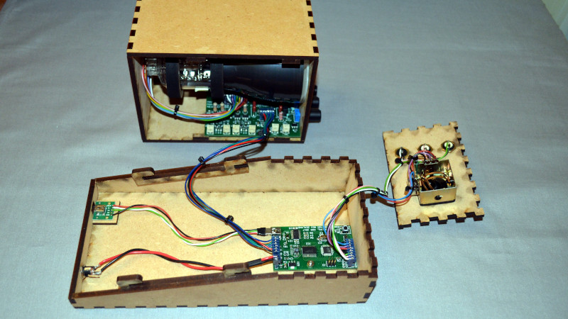
I meant no disrespect to this project, it’s a thing of beauty! It’s very impressive, and I personally like the HV power supply design. It’s all a crazy amount of effort, all the way down to the case, the laser cut burn marks are cool!
I was comparing the vector generator of this design to the VG of the old arcades. This would be similar to the role the ATmega328 is doing here. Apples to apples, but a big difference in the “apples” performance.
Asteroids for instance used a Vector Generator processor (a PROM based state machine) designed using only TTL logic, with an instruction set that not only had “Draw vector” instructions, but had a stack and could call subroutines and draw images from ROM and return. There were no divide instructions, so vector slopes were calculated using shift registers. Hardware counters were used to clock the length of the vector. This was all done with no input from the from the 6502. You could stop the CPU and the screen would continued to be refreshed.
Each pixel was drawn at a 1.5MHz clock rate. It used a sample and hold design to latch the DAC’s outputs to help get around DAC distortions.
The pixels where drawn at the same speed as the CPU’s clock! The 6502 wrote a vector “program” into shared RAM, the state machine used DMA to access the memory (all done in TTL logic). The vector display ended up being the equivalent of 1024×728 pixels, and could be refreshed 30 to 60 times per second, depending on how many vectors were drawn.
That’s what I meant by hardware!
The ATmega328 in this design is running at 16MHz. To draw a vectors at a 1.5MHz rate, you’d have to do it in under 11 clock cycles per step, and at a minimum you’d need to:
Test to inc X
inc X if true
Test to inc Y
Inc Y if true
Write X to DAC
Set WR high
Set WR low
Write Y to DAC
Set WR high
Set WR low
Set LDAC high
Set LDAC low
Dec vector counter length
Loop if not done
That’s at least 14 clocks, with nothing left to access I/O, read the next vector, etc. so I’m pretty sure this is not generating vector steps at 1.5Mhz.
I few years back I designed and manufactured the Zektor ZVG to run vectors on the old vector monitors at full speed (https://www.youtube.com/watch?v=-24WHLnI5ZE), and it’s hard to draw vectors as fast as they did back in the day! I also used AVRs, but used an analog vector generator that can run much faster than a firmware control digital VG could, at least at the time. But I think you can finally pull off a, full arcade speed, digital vector generator – like this project uses, if you move to something like a 500MHz ARM processor.
Much more effort went into this project than the ZVG, mine was just a PCB board and some trick firmware… I’m truly impressed.
For those interested, an excellent overview of how the old vector generators work is on this site written by an ex Atari hardware engineer: http://www.jmargolin.com/vgens/vgens.htm
What you describe reminds me of the digital storage in Tektronix 7L14, 7L5, 492, and 496 spectrum analyzers. This was in the 1970s and 80s, before digital ‘scopes were a common thing, but by refreshing from digital memory, they saved a lot of money over using storage CRTs. These were basically vector generators. What was stored was the vertical position for each of around 250 horizontal positions on the sweep, and these were fed to a DAC to get the deflection voltage. But that wasn’t good enough for Tek – this would have resulted in a display full of dots, and they wanted the dots to be connected together. So they had a vector generator implemented in 74-series TTL. This took the difference in Y between the previous dot and the next one to be displayed, and fed a precision integrator with this, and gated the integrator for a precise amount of time, so that it drew a straight line between the two points. At the end of the integrator gate, the output was clamped to the DAC output voltage so the points were accurately placed and there was no cumulative error. I never appreciated this particular part of the circuit until I had to repair one because the vectors were overshooting, causing the waveform to be very spiky. This turned out to be because the capacitor in the integrator had dropped in value, so the vectors were being drawn too fast, continuing past their destinations by almost 50%. In the same era, Tektronix made graphics terminals (4010 series) that used direct-view storage tubes, and these similarly used precision integrators to generate vectors, only these had to be done in X-Y pairs. It was kind of magic to see how well these worked.
Tha’s cool, I never realized Tektronix had done that! The nice thing about a scope is you don’t have to move the trace to a bunch of unconnected vectors, it’s all one line.
After Asteroids, Atari wanted to get more vectors on the screen, and vector monitors were getting faster. The 1.5MHz clock rate was as fast as the technology was going to let them run a Digital Vector Generator, so they switched to an Analog VG, and it ran the same way as Tektronix (without the ending DAC clamp — and there was cumulative errors!). It used a gated integrator, and a precision timer, to draw the vector. By carefully choosing your current and capacitance, you could draw a vector much faster than you could with the digital stairstep approach. To account for the capacitor tolerances, they had a “line-length” adj. going into the integrator that allowed you to match the drawing speeds to the precision timer. To deal with the drift errors, there was a “zero” function that shorted the integration capacitor, and re-centered everything. It was called at least once per frame.
The choice of the integration cap was critical. They tested a lot of different caps to find a type that worked well. Jed (the Atrari engineer at my previous link) explains all the issues they had.
A couple years ago B.C. (Before Covid), I was at an Arcade game convention in California (http://www.caextreme.org/). There was an exhibitor there that was working on manufacturing new X/Y arcade monitors. They had lined up a company to build the CRT’s (I guess you can still have these made if you have the quantity), and they were either working on, or had already sourced a place to have the yokes wound. I wonder what happened to them? (I wish I could remember the name of the company!)
They were using a clone of the old Arcade electronics to drive the yoke, cathodes, HV & focus voltages. If they really pull this off, it opens up an opportunity for modern vector controllers and drive electronics. Even back in the day, the designs were built as cheap as possible, with a lot of “Ahh, the focus is good enough, ship it!!” attitude.
And there’s this guy: https://hackaday.io/project/2871-build-an-arcade-xy-vector-monitor
Fun stuff!!
Holy Flash! That’s amazing. I love the wooden Apple II case and would like to test DAC-1, UNISURF, and Unigraphics on this machine. Is there anyone else who wants to play the original Spacewar! game? :D
You haven’t seen this advanced Bezier vector portrait of the original CAD UNISURF project leader, don’t you? It was made with Free Software!
https://gfkdsgn.wordpress.com/2021/01/06/pierre-bezier/