Measuring the usage of domestic utilities such as water, gas or electricity usually boils down to measuring a repetitive pulse signal with respect to time. To make things easy, most modern utility meters have a pulsed LED output, which can be used to monitor the consumption by using an external optical sensor. But what do you do if your meter isn’t so cooperative?
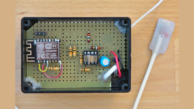
That’s exactly what [Francesco] had to figure out while developing the non-invasive gas tracking system he calls ESPmeter. His meter might not have an LED, but it did have a magnet attached to the counter disk which activated an internal hall sensor. With some hacking, he was able to attach an external Hall-effect sensor to pick up this magnet and use the signal to monitor his daily gas consumption.
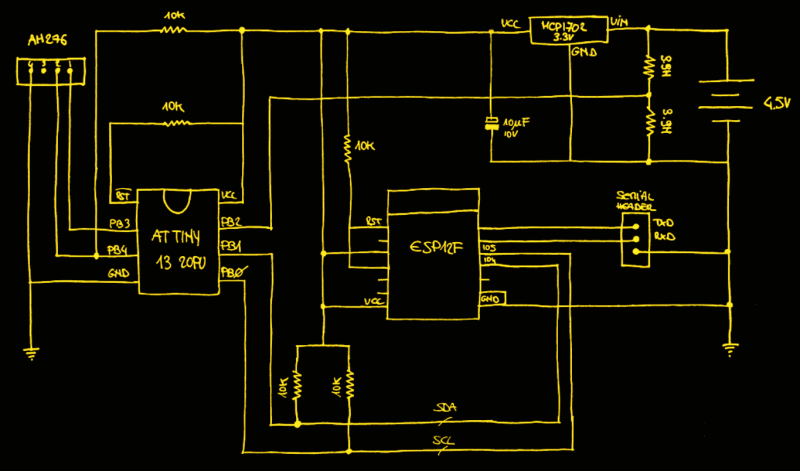
A big stumbling block in such projects is the issue of powering the device for an extended period, and remembering when it’s time to change the batteries. With the clever use of commonly available parts, he was able to reduce power consumption allowing three AA batteries to last about a year between changes. For one thing, he uses an ATtiny13 to actually read the sensor values. The chip doesn’t run continuously, its watchdog is set at 1 Hz, ensuring that the device is woken up often enough so that it has time to power up the sensor and detect the presence of the magnet. Battery voltage is also measured via a voltage divider connected to the chip’s ADC pin.
At regular intervals throughout the day, the ESP8266 polls the ATtiny13 to pull the stored sensor pulses and voltage measurement. Then at midnight, the ESP transmits all the collected data to a remote server. Overall, this whole scheme allows [Francesco] to reliably gather his gas consumption data while not having to worry about batteries until he gets the low voltage notification. Since the data visualization requirements are pretty basic, he is keeping things simple by using Plotly to display his time series data.
If you are unfortunate enough to have an even older meter which doesn’t use optical or magnetic rotation sensing, you can use a disassembled mouse to keep track of the Gas Meter.


Combining an Attiny with a bigger Esp, how elegant :-)
Great project, Francesco!
By some cosmic coincidence, I happened to just make a very similar device this week, built around a LIS3DML magnetometer. It’s not necessary to rely on a magnetic coupling. As the steel bellows in the meter expand and contract like lungs, they sinusoidally alter the magnetic field detectable outside the box. (My meter is American Meter AC-250, really common internal design that probably hasn’t changed much in 100 years).
I count the “breaths” and periodically send the count of them off to an Influx db for later visualization.
Love this Francesco’s clever methods of saving power. In my case, I had power nearby, so my build is just a USB-powered ESP32 + LIS3DML in a little box I taped to the back of the meter body. https://github.com/jeffkowalski/pulmometer
I went this route after scratching my head for over a year trying to decode the signal that the Aclara Star Hexagram retrofit sends to the gas company. Regrettably the excellent RTL-AMR project doesn’t work with this MTU, which broadcasts FSK on 462.4125 MHz 4 times a day.
What’s really remarkable is the insight into my gas usage. I have forced air heater, radiant floor boiler(*), domestic hot water(*), range top, and barbecue on gas. But a very significant amount of the gas that’s consumed is used just to keep the pilot lights burning on the older appliances(*).
Funny how these things work. Coincidentally, I’m also working on a design using the same LIS3MDL magnetometer to sense water meter usage, and was wondering whether the same approach would work for gas.
By further coincidence, the (patented) commercial Flume water meter sensor ALSO uses LIS3MDL as a sensing element. Go figure.
As an aside, the Flume device is a fascinating bit of kit that looks honestly like they put their prototype together from Sparkfun modules and changed basically nothing for the commercial version. ATMEGA328 no doubt originally running Arduino firmware if not still, RFM69 radio modules, an ESP8266 in the base station. Except for their neat cloud based tracking system, which is no doubt what you’re paying $200 for, you could put the whole thing together for under $50.
Yes! I have a Flume, and was inspired by their water meter to do the same for gas. I actually really like the company. The product was initially a college master’s project turned commercial. Good for them! They’ve been really responsive, have a great API, and their new version looks like there’s some more engineering. You’re totally correct about the commodity hardware, but again, good for them! Remember, it’s often what you *deliver* that’s more important than what you *invent*. This was the first and only utility-sanctioned (yes, I got a 50% rebate from the water company) device that I found. Good for them!
Hi Jeff, I have the same Meter and came across your comments while building something like you already did :) Where on the meter did you attach the magnetometer?
Thanks
Use a reed switch as interrupt input to esp8266 and the attiny is not needed and then send the wake up / counting pulse every wake up. Debounce not really needed
Thanks for your comment! That was in fact the very first thing I attempted but there were two problems with this approach: 1) I could not find a reed switch sensitive enough to be triggered by the magnet (which is extremely weak, barely detectable even by the hall effect sensor) and 2) this would have booted the ESP at every loop of the counter, potentially once every a few seconds during winter when the gas flows for hours; this would have been too expensive on the batteries.
Nice work! I’m currently making a WiFi IoT button, and our designs are very similar- down to combination of the ESP-12F and ATTINY.
I appreciate the thorough wtiteup, including the notes about the voltage divider- though I’ve read an additional cap on ADC pin can help.
I just monitor the gas furnace “flame on” LED and calculate gas consumption. Nodemcu12e.
We have Gas furnaces, a gas boiler (for radiant and hot water), and gas appliances (stove, clothes dryer, etc.)…
That wouldn’t work for us… :)
I build EXACTLY the same thing a few months ago. Problem is that the ESP tends to hang up in its WiFi code after a few weeks. Couldn’t figure out why, so I trashed the whole contraption.
I always put in a little code to restart the ESP when WiFi drops.
“`
if (WiFi.status() != WL_CONNECTED)
ESP.restart();
“`
I did just that, not in a loop that is but with an event and more (wdt, etc) still it would hang someplace for no reason after a while (esp32 that is).
Hi
Nice idea, it got me curious : why not using an interrupt to wake up the attiny13 ?
Cheers
IME a lot of people are too scared to run interrupts. I have seen some horrendous things using polling.
Thanks!
Well, in fact the Tiny wakes up either via an interrupt from the watchdog or from the I2C pin.
https://github.com/francescovannini/espmeter/blob/490bf8f0dedf8d13d47cfcab28daa34ba78f9fb0/tiny/main.c#L54
But I guess your question is more like: why didn’t you keep the Hall effect sensor always on and trigger an interrupt with it? I tried and discovered that I was saving more power by doing this way; you don’t need the sensor always on in fact, you just need to turn it on when it’s probable that the magnet would be in its proximity. And the sleeping Tiny absorbs much less than the sensor always on; so the Tiny wakes up via the watchdog, powers up the sensor, records the pulse (if magnet is there) and it goes back to sleep. The Tiny would have to be sleeping anyway, so adding an always powered up sensor could only consume more power.
I was curious about this too. As Francesco noted below the ~10mA it takes to run the hall effect sensor far exceeds the power wasted by polling the sensor. It might be worth checking the catalog of your favorite supplier for a sensor that uses less power.
Using an esp32 the magnetometer is built in and the ULP coprocessor too, it would consume less current than the attiny and it would be much simpler
Sorry to pour cold water on your inventive solution, but the supplier might take exception to anything attached to the meter, seeing it as if it was a magnet. Slowing down the electricity meter disc with eddy currents induced by field from an external attached magnet is a common way to reduce bills. Arguing your case would be inhibited by the general lack of science knowledge coupled with unwillingness to believe from their legal department. Even if you can prove your case in court it could be greatly costly in the long run.
I should think twice before attaching anything to an incoming supply meter.
The fine art of reading:
“With some hacking, he was able to attach an external Hall-effect sensor to pick up this magnet and use the signal to monitor his daily gas consumption.”
His meter has an INTERNAL magnet, that pulses an INTERNAL Hall effect sensor.
Het attaches an EXTERNAL Hall effect sensor, not a magnet.
Ironic reply, that.
Re-read his comment.
His point is that your average meter reader is going to not know what this is. But they do know there is a history of slowing meters down with magnets. Therefore, expect a lot of attention from the gas company when this is noticed.
Yah, that.
Are there a mobile/coupler version of these meters? In my country its the norm to have the 50kg propane tank taken to be filled in a station and then brought back. I’ve seen a couple of approaches with temperature and noise ressonance but they dont seem reliable or more reliable than old measurement between the flow.
The best approach to this that i’ve seen is electronic scales, I know a few places that use this same option as it also doubles as verification the tank was filled to spec without attaching anything to it, i’ve seen a lot of places that under supply.
Valid point, however:
1) the idea was to build this thing with whatever I could find in my junk drawer; the hall effect sensor has been salvaged from a PC fan and isn’t designed for ultra low power consumption
2) even if you use a very low consumption sensor, the Tiny would still be there sleeping, so you would only add more consumption to get essentially the same result.
Granted I’m not sure how low a very low consumption sensor is, but at some point the savings from not having to wake the attiny at regular intervals would outweigh the low constant consumption of the sensor. Back of the envelop I think the hall effect sensor would need to draw less than 1μA for this approach to result in any savings.
I’m counting my gas consumption, too. However my gas meter does not have magnet signal. I solved it the “optical way” (known from some power meter solutions). The last digit on my meter does not show the numbers from 0 to 9, but 0-4 and 6-9. The 5 is replaced by a small reflector. A reflective infared optical sensor mounted in front of the last digit notices the difference in the reflections and gives me an impulse for calculating the consumption.
I’m sure that the show solution can be easyly combined with this alternative for reading the impulse.
My meter has a little shiny magnet glued to the number 6. At the very beginning I thought to take the same approach you took, then out of curiosity I just tried putting a sensor very close (I think I’ve tried with my phone compass sensor if I remember correctly) and I realized it wasn’t just shiny, it was also magnetized.
I really liked this one, had some fun trying to find room for improvements.
I would eliminate the 10k from PB4 and instead use the internal pull-up.
I doubt there is much utility in measuring the battery voltage every 5 minutes if the battery is to last a year. A few times a day, or even just once a day, may be all that is required.
Since gas is often used for heating, adding a temperature sensor makes sense.
It’s probably worth investigating having the attiny / sensor run directly from the battery and periodically switch the linear regulator on for the daily update. I estimate the average power required to collect data from the sensor in the ballpark of 10uA (the typical value for the ESP12 in deep-sleep).
The potential power savings are significant, but it does introduce some complications:
The timing of sensor readings and the powering on of the ESP12 will be subject to the drift of the attiny’s internal oscillator
The attiny and ESP12 will be operating at different supply voltages, so the I2C bus will need some kind of level-shifting
The attiny will need to measure the battery voltage and will need to compare it against a known reference (instead of VCC).
Outside of the level shifting, these problems could be mitigated in software – the ESP could tell the attiny how many seconds to run before the next update to compensate for long term drift. The internal 1.1V voltage reference could be used to monitor the battery voltage at the expense of some resolution.
Of course, adding an external clock source and voltage reference are also options.
It looks like the VCC value is only captured once every 3 hours – which is much more reasonable than what I thought was happening.
Thanks for your comments and ideas!
Indeed, the 10k on PB4 is out of caution, it would probably work fine without.
Battery is measured every 3 hours, but in fact it’s still too much; once per day would certainly suffice. I sampled it every 3 hours because I was expecting a faster drop but instead it’s been a few months and it barely moved from the maximum, so definitely can be sampled daily.
Certainly cutting the ESP power entirely when isn’t being used for WiFi would save a lot of power, but unfortunately there isn’t enough space in the Tiny RAM to store an entire day. So content of the Tiny is dumped ever 3h and kept in the ESP “RTC” RAM, which needs to be powered to be able to keep the data. But using the flash could be an option, although it would shorten the ESP life, probably.
The time drift is in fact still a problem, in both the Tiny and the ESP. The ESP is horrible in time keeping, the RTC is simply ridiculous; there is a simple calibration routine in my firmware to try to compensate for that, but it’s still far from being perfect. But in the end it doesn’t need to be ultra accurate anyway, once the data is aggregated per hour the time drift has a negligible impact.
Good point – the attiny’s memory is indeed tiny!
Ignoring the possibility of turning the ESP off for now, would it be possible to have the attiny wake up the ESP when its memory is full using one of the I2C pins? That would cut down on the number of times it has to exit deep-sleep from 24 to 8.
If you get clever about how you store the readings, I figure you could store 12 hours of readings in one 30-byte buffer of SRAM that gets copied out into two 30-byte buffers in the EEPROM. I can share the details if you are interested. This would reduce the number of ESP wakeups to just 2 per day. At a rate of 1 erase every 12 hours, I estimate it would take more than 30 years to exceed the EEPROM’s rated durability.
Regarding keeping time, if you check out Figure 19-57 in the attiny’s datasheet you will see that the frequency of the watchdog oscillator drifts with temperature. Since you do not need to check the battery voltage very frequently, you could have the ESP monitor it and free up PB2. You can then collect temperature data to report and/or use it to adjust the duration of a 0-100ms delay in your event loop to keep the time between sensor readings more consistent. You could also adjust this delay to compensate for long term error when the ESP gets the precise time from the internet.
Lastly, you could shave some power by reducing the speed of the attiny most of the time and switching it to full speed when the ESP initiates I2C and then reducing it again once the communication is done. Running faster lets you sleep sooner, but running slower does save some power overall (see Figures 19-1 through 19-3 in the attiny’s datasheet). The savings become more significant if the attiny is awake but just waiting for something to happen (say for an ADC conversion or a delay). How slow you can go will depend on how fast your code needs to execute to ensure it will catch every revolution of the meter wheel.
All in all, cool project! Again, I had fun thinking about all of the different possibilities.
Francesco, great stuff. I find your division of labor between a MCU and an ESP very smart. Of course… this is a bit of a confirmation for me (shameless self-compliment). I’m monitoring my water-meter with a magnetometer hooked to an atmega328 that sleeps and waits. When the meter spins, the logging starts for 1 minute at a minimum. If the meter keeps spinning, the logging continues every minute until the event is over. After 20 minutes have been buffered, I bulk-load the data to thingspeak via an ESP. So far there are about 5 bulk-loads per day. It is all outdoors and remote from mains power, so I use two LiOn 18650 cells; voltage is reported once per bulk-load. I embedded the sensor/328 combo in a epoxy-filled 3-D printed saddle that is strapped to the water-meter.
With your encouragement, I’m now testing my gas meter for the most sensitive location (seems to be right off the top between the inlet/outlet pipes). Anyway, thanks for sharing.
Hi. This is great stuff, i’ve been wanting to solve this problem for so long. Would this solution integrate with Home Assistant?
Thanks.