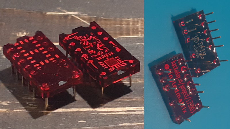
Back in the 1970s, there were a huge variety of esoteric LED displays on the market. One of those was the DIP-packaged TIL311 from Texas Instruments, capable of displaying hexadecimal, from 0-9 and A-F. While these aren’t readily available anymore, the deep red plastic packages had some beauty to them, so [Alex] set about making a modern recreation.
The build consists of a small PCB fitted with 20 LEDs, and a STM8S microcontroller to run the show. This can be used to emulate the original decoder logic on the TIL311, or programmed with other firmware in order to test the display or enable other display functions. Where the project really shines however is in the visual presentation. [Alex] has been experimenting with potting the hardware in translucent red resin to properly emulate the look of the original parts, which goes a long way to getting that cool 70s aesthetic. Attention to detail is top notch, with [Alex] going so far as to carefully select pins that most closely match the square-cut design on the original TIL311 part.
It’s a fun build that could be useful for a project when you can’t get working new old stock. We’ve seen similar efforts for Nixie tubes in the past. Video after the break.


The Yaesu FT-301D ham transceiver uses these, and they die. If anyone is still preserving that old rig, they could use some of these.
Yeah, those are pretty cool. I’ve still got a bunch of them that I use in projects.
I have a bunch of HP’s hexadecimal version of these.
They sure love gulping electricity.
Love and hold them on stock too .. but would never use them for actual projects :-\
Today’s LEDs are quite a bit more efficient then they were then, so these could be made to match the luminosity of the originals while significantly reducing power consumption. It looks like the digits are larger than the originals, which is a good thing, but it means you’d probably want to change them as a set. Also, I don’t remember what the originals cost, but one could probably sell them on Tindie for less today, even in today’s dollars. I mean, if one really wanted to go into moderate quantity production.
Bravo!!!!! when I was about 6 years old, my Dad made a signal generator that used a version of those (the ones with the built-in decade counter) –to this day (45 years later) I still have that board counting in my lab.
They were expensive but what made them stand out was the latch/decoder/driver were inside the package. So 2 ICs and the readout together in one package.
There was more than one in the series, did the other one have a counter built in? Or the other just 0-9?
It made a big difference when you needed counter/latch/decoder and readout for each digit, not just for frequency counters, but clocks (using external counter), DVMs, whatever.
I don’t remember a lot that used the hex capacity, Steve Ciarcia had a project in Byte that made use of it, but nothing else jumps out.
I don’t recall anyone choising them for the actual display, just the greater integration.
The original 1802 computer featured them.
http://www.cosmacelf.com/history/
Exactly! I still have my 1802 ELF, but when I built it I used some MItel CMOS decoders (I think they were 4368) for hex support using standard 7-segment displays. Alas, the HP 5082 on the original ELF were nicer, indeed.
Actually, the original Elf used HP 6082-7840 hex displays. They are very similar to the TIL311 but have the pins along the top and bottom rather than the sides.
Note to builders: The Motorola MC14595 is a CMOS binary-to-hex decoder chip that does the same job as the internal chip on the TIL311. If it can be found in surface mount, these displays could be made without a microcontroller (and much lower power).
Depending on what it is used for, It would be hard to meet the timing for the latch of the original part using the STM8 as you would have to deal with firmware overheads. i.e. won;t be a drop in 1:1 replacement for anything that runs fast e.g. directly to a bus.
Some of the Microchip PIC parts have Parallel slave port (PSP) which can be latched externally while newer ones have essentially programmable logic. Some of the lower end small packages ICE40 FPGA might fit the bill.
https://en.wikipedia.org/wiki/Parallel_slave_port
They only need to meet the timing requirements in an actual use case, not the theoretical max specs of the latch.
And if the microcontroller is clocked fast enough and the code is efficient, you’d never know.
I would love to see one of those driven by one of those tiny 100LUT FPGA, that would be pretty sweet!
Another option would be an EEPROM, simpler than an FPGA.
How would that work? I wasn’t aware EEPROM had any executive capacity. ie, it doesn’t “do” anything; it’s just memory.
You can implement an arbitrary truth table inside any suitably-sized EPROM, mapping your chosen set of digital inputs to outputs with known maximum latency. And you can make a sequential machine by looping some outputs back to inputs.
But no latch unfortunately.
Latches are cheap. This was how we did things before microcontrollers became easy.
It doesn’t “do” anything – you just use it as a look-up table. For x input, you get y output. So with a ROM (of any sort) and a latch, you can put the current state on some of the address inputs, and other inputs that would change the state on other address inputs. You program the ROM by determining all possible combinations of “current state” and inputs, to give the desired output, either encoded as a state number, or as direct outputs, or both. The number of bits you need is determined by how many bits it takes to express the state of the machine, plus direct outputs. The number of words you need is determined by how many bits it takes to encode the current state and the inputs that can change the state.
I used an EPROM once to make a digital compass without using a computer or microcontoller. I ran the outputs of X and Y hall sensors through A to D converters, and programmed the EPROM to “calculate” the arctangent of Y/X, AND to convert the result of that into degrees in BCD. (My choice, but I could as easily have had it output to N, NE, E, SE, and so on LEDs even more easily.) It was fun, and it worked beautifully, first try. For the contents of the ROM, I wrote a BASIC program that did the calculations and produced output in the Intel hex format that our EPROM programmer at school needed.
The original IBM PC used a small PROM to decode the upper CPU address lines to DRAM bank RAS lines. DIP switches set 2 address pins to choose the DRAM size. Programing a new PROM gave mixes IBM didn’t support. Fun times.
Cool. Did not know that.
I have one that is in a 14-pin package, with a
VCC pin,
GND pin,
Enable pin,
(displays 0-9 depending on which pin is high),
And a decimal point pin.
Took a while to figure out the interface, I wasn’t expecting a ROM segment look up table.
That was the big selling point when they were introduced – that you didn’t have to put separate BCD/binary to 7-segment decoders into your project. It was how they justified the price. The cost was about the same as a 7-segment module plus a BCD/7-segment decoder, but the reduction in PCB area was expected to be enough, and in many cases it was.
I bought a bunch of NOS til311 for some retro computing. Wasn’t cheap…
Still listed on AliExpress. About US$6 each…
Awesome workBe sure to include a 50 ohm, 1 watt resistor across Vcc & Ground in order to mimic the power draw & heat output of the originals!
muahahahaha spot on !!!
I use to undervolt them though, it helps :-)
I looked. The TIL308 was only 0-9, and no counter. The TIL-306 added a bcd counter. Some of my searching reminded me that there were variants, whether the decimal point was on the left or right.
I’m too lazy to check whether the TIL-311 had variants.
7 segment readouts could always display hex, as long as you could live with odd results. The coolness of the 311 is the extra segments to allow proper display of A-F.
But I still say it was the better integration that made these devices valuable. And since you paid more for them, the value wasn’t clear cut.
Okay, I have to be the pedant. I don’t want to, but I’m seeing a useful word degraded, and it’s something that’s happening all over, not just here. The word is “transparent”, as compared with “translucent” and “clear”.
It seems that many people are reluctant to use “transparent” when describing colored objects, apparently believing that transparent means clear. So let me um, clear this up:
Clear: something that you can see clearly through, that does not change the color of it. And by “clearly”, I mean if there is text behind the thing, you can read that text.
Transparent: you can read through it, but it may alter the color. Beer bottles are transparent, whether clear, brown, or green. Do not even imagine that there is such a thing as a blue beer bottle. But I digress.
Translucent: diffuses light, so you cannot easily read through it. May also alter the color.
In the photo at the top of this article, we can distinctly make out the shapes of the LEDs embedded in the red resin, so these are transparent, NOT translucent.
Here’s what the Oxford dictionary says:
translucent: (of a substance) allowing light, but not detailed shapes, to pass through; semitransparent.
‘fry until the onions become translucent’
transparent: (of a material or article) allowing light to pass through so that objects behind can be distinctly seen.
‘transparent blue water’
In fact there is a transparent blue beer bottle, made in Newfoundland Canada… Iceberg Lager… It’s not bad.
Here’s a link: https://quidi-vidi-brewery.myshopify.com/collections/lagers/products/iceberg-beer-6-pack-bottles (May have to click through age related question.)
So you can include blue beer bottles in your list. :)
LOL! I KNEW I could get someone to bite on that!
To add more, some materials can be transparent to visible light but translucent to other EM frequencies. Ordinary window glass is translucent to infrared. An IR camera cannot resolve an image through it, despite what many police/crime shows on TV portray. There are some plastics (ye olde shopping bags for one) that are translucent or opaque to visible light but transparent to infrared. Materials that are transparent and clear to both visible and IR (and likely ultraviolet) are used for things like windows for missile sensors.
Huh. I just recently used one of the vintage TIL311s I had lying around in a project: my homebrew version of the Glitch Storm, an Arduino-based bytebeats explorer (the creator has open-sourced it, and also sells it on Tindie — you can look it up there if you want details).
As designed, the system selects from sixteen algorithms, with which one you’re running displayed, in binary, on four LEDs — which made it, in my mind, a perfect fit for the TIL311. The mod was as easy as you’d think, and it looks pretty snappy.
Post the pictures !
I made some posts about it on my tumblr — the photos, text, and audio all come up at https://taperwolf.tumblr.com/tagged/glitch%20storm .
(The case is a little janky, but it kind of fits the “glitch” aesthetic, and it stands as an example of projects undertaken without access to my usual makerspace under lockdown.)
Yet another amazing job by Alex !!!
This project started as PICTIL https://hackaday.io/project/8270-pictil : I created it because I needed it, and Alex chimed in, then provided more and more work, until I simply handed the project over to him (so I could work on DYPLED). He makes me proud :-)
Great job on that resin casting! Just like a bought one!
Great job! And i like that it does HEX characters correctly.
Wow, they came out great! The tint of the resin looks perfect and it’s neat that you were able to make the mold from the original display.
https://www.youtube.com/watch?v=2Ah015OB4JQ
here I am using four TIL311’s and with only a 5 pin connector (pwr,gnd,data,clock, an latch).