[Tom Stanton] has been messing around with compressed air power for a few years now, and most of his work focused on piston engines. He likes using 2-liter soda bottles as lightweight tanks but their capacity is limited, so the nozzle can be a maximum of 1 mm in diameter if he wants to produce thrust for 30 seconds or longer using a turbine. Pelton turbines have been in use for a long time, especially for hydroelectric systems, and they use small diameter nozzles, so he decided to experiment with a pneumatic Pelton turbine. (Video, embedded below.)
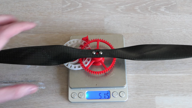
Pelton wheels are water wheels with specially designed buckets to efficiently extract energy from a high-velocity jet of water. [Tom] 3D printed several geared Pelton turbines and started doing bench tests with a propeller and a load cell to gather empirical data. With the help of high-speed video of the tests, he quickly realized that the turbine efficiency is highly dependent on the load. If the load is too small or too large, the moving air will not come to a complete standstill, and energy will be wasted. [Tom] also suspected that some moving air was escaping from the bucket, so he created a version that enclosed the buckets with a ring on the outer perimeter, which increased the peak thrust output by 65%. Compared to his diaphragm air engine design, the peak thrust is higher, but the overall efficiency is less. [Tom] believes there is still room for improvement, so he plans to continue working on the Pelton turbine concept, with the hopes of building an air-powered model helicopter that can lift off.
One comment that came up a few times with his piston engine designs is whether venting the air straight out the nozzle, without a turbine or engine in the way, would be a better option. [Tom] tested this in the bench, and the straight-through nozzle was four times less efficient than the turbine. The reason for this was addressed in the comments on our article on diaphragm air engine and discussed on the Hackaday podcast. It’s an impedance matching problem, and an engine or turbine converts the small volume of high-velocity air into a large volume of low-velocity air.


Pelton wheels can be tricky to design, but for a general rule of thumb, the peak efficiency is when your buckets are moving at half the speed of the fluid stream.
My rule of thumb is simply to use 50 ohm buckets to get reasonable allround performance in most cases.
That only works for coaxial penstock.
When using a ladder-line penstock, you should match for 300-600 ohm buckets.
:-)
Unsurprisingly, the actual case CAN be reduced to a mechanical impedance matching problem.
But there’s a far simpler reason: The stream is supposed to lose all of its forward momentum while it’s pressing against the moving bucket. The water loses its kinetic energy over some distance (hence why the curved, not flat, bucket), and the average speed over that distance, assuming linear deceleration, must be half the starting speed.
If you invert the case and think of the water going backwards, you can think of it like a rope-and-pulley lifting problem. One end of the rope is fixed stationary, while the other end is being pulled – how fast does the pulley lift up relative to the speed of the rope? At half the speed of course.
Similarily you can describe RF impedance matching problem in terms of capacitors, inductors and resistors pulling electrons using ropes and pulleys :-)
“[Tom] also suspected that some moving air was escaping from the bucket, so he created a version that enclosed the buckets with a ring on the outer perimeter, which increased the peak thrust output by 65%.”
Nooo, he changed to a Turgo design because he was having problems precisely aligning the air jet nozzle with the middle of the Pelton buckets.
Watch the video at 5:30
Fluid flow impedence matching?
Count me out
This might be why he doesn’t get as good of performance.
Wikipedia:
Because water is nearly incompressible, almost all of the available energy is extracted in the first stage of the hydraulic turbine. “Therefore, Pelton wheels have only one turbine stage, unlike gas turbines that operate with compressible fluid.”
https://en.wikipedia.org/wiki/Pelton_wheel
Just use Flammable Gases ignite it then use the expanding thermo-engery to turn a turbine attached to a …….
Oh Wait that’s a Turbo prop.
” It’s an impedance matching problem…”
That just means you are not utilizing the compressed air properly. There are more efficient methods for directly converting the compressed air into thrust than mechanical means. You’ll need properly designed nozzles as well as active flow/pressure control.
But this project is doomed either way unless it is tethered to the ground. The energy density of compressed air compared to the mass density of the vessel needed to contain it is such that you’ll only fly for a short amount of time no matter how you design it. As you increase the pressure to increase energy density, the minimum mass density of the vessel will increase proportionally. If you include a safety factor, you end up with very little flight time. You need a different energy source, or in addition to the compressed air (like heating it with a chemical fuel) to really get any flight time. At that point, you might as well use an engine and get air for free from the environment, and you’ve invented a helicopter.
> you’ll only fly for a short amount of time = failure
Actually, you can have a bit of fun even for a short amount of time.
Did you see how much Peter Sripol laughed with his rubber-band powered helicopters?
Bonus points for a phase-change gas as fuel. There were CO2 (piston) model aircraft engines that ran on tiny tanks and worked reasonably well (if they didn’t freeze into an icy mess)
http://www.gasparin.cz/page.php?page=co2/motors/history&lng=en
Would vortex jets help here?
Seems to me a single stroke piston driven directly through the compressed air cylinder driving a rack and pinion to turn the prop gearing is about as efficient as it can get. Use all of the air. if it achieves vertical lift into lower pressure air, the difference in pressure could help it along, You get more out of your charge, but diminishing returns due to the lower density of air against the prop. And that’s going to take a super efficient prop designed to deform at higher rpms for the torque vs velocity trade off. CV prop?
Using a compressible fluid in non-laminar flow to drive a Pelton wheel is not a good idea to begin with. I wonder why he put so much effort into that bad idea… YouTube eyeball harvesting maybe?
Don’t the curved sides of the paddle just allow water to exit easier without doing as much work or am I missing something?
Check out my research wind turbine at flyingdiamondsenergy.com which is a variation of a Pelton wheel. We are at the beginning of research and do not know what the final wind trap (bucket) will look like. Research continues. Note the patented variable drag feature built into the design. High Drag on the power side and then low drag on the recovery side.