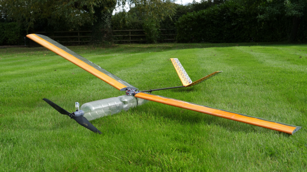
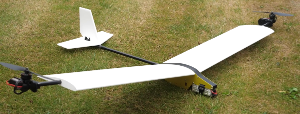
There’s something to be said for a simple wind-up, free flight model airplane. With no controls, it must be built very well to fly well, and with only the limited power of a rubber band, it needs a good, high-lift design without much superfluous drag to maximize flight time. There’s also something to be said for modernity though, and prolific hacker [Tom Stanton] puts them together with this supercapacitor plane.
If that sounds familiar, it’s because [Tom] did this before back in 2023. But for that first attempt he converted a commercial R/C toy rather than a plane optimized for low-power free flight. Just like with the best rubber-band machines, his goal for the new production is more flight time than winding time. Plus lots of views on YouTube, but that goes without saying.
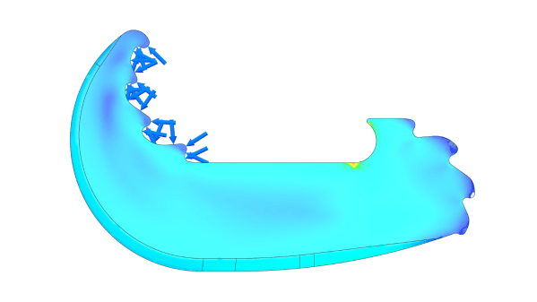
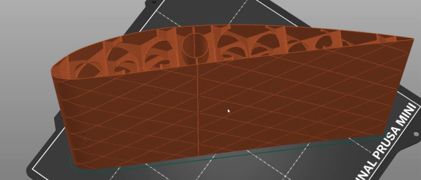
Thus this machine is smaller and lighter than the previous iteration. Rather than balsa and tissue like the free-flight aircraft of our youths, [Tom] is using 3D printed plastic for the structure. But he’s got a neat hack built in: he’s printing the wings and control surfaces directly onto tissue paper, eliminating the bonding step. Of course that means his wings are printed flat, but a bit of heat and some bending and he has a single-surface airfoil. Single-surface airfoils are normal in this application, anyway: closed wings add too much weight for too little gain. If you want to try the technique, he’s got files on Printables.
Another interesting factoid [Tom] discovered is that the energy density of supercapacitors decreases sharply below 10 F. As you might imagine by the square-cubed law, bigger is better, but the sharp drop-off dictated he use a single 10 F cap for this build, along with a micro motor. Using the wind-up generator from his previous build, he’s able to get 45 seconds of flight out of just 4 seconds of cranking, a good ratio indeed.
[Tom] seems to like playing with different ways to power his toys; aside from supercapacitors, we’ve also seen him finessing aircraft air motors — including an attempt at a turbine for a model helicopter.
Continue reading “Electric Wind-Up Plane Uses Supercapacitors For Free Flight Fun”