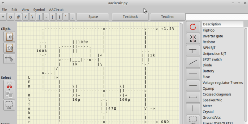
We wondered recently about those crude ASCII schematics you see in some documentation — are there any dedicated schematic-focused tools to draw them, or are they just hand-crafted using various ASCII-art drawing tools? To our surprise, there is such a tool. It is called AACircuit and was developed by [Andreas Weber]. It has a history going back to 2001 when it was first introduced as ASCIIPaint. Be forewarned, however, the quality of the code may be questionable. According to the notes on [Andy]’s GitHub repository:
WARNING: a lot of spaghetti code ahead
This code was created in 2001-2004 when I taught Borland Delphi 3 to myself. It contains many, many global variables, unstructured and undocumented procedural code and bad variable names.
If you don’t want to wrestle with old and sketchy object-oriented Pascal code, you’re in luck. [Chaos Ordered] has made a Pythonized version which you can get from his GitHub repository. We tried it out and got it working on Ubuntu in short order (after wrestling with a pycairo dependencies). This might not be everyone’s cup of tea, but it has some uses now and then. While we wouldn’t want to document a computer motherboard with ASCII schematics, it’s great for a quick-and-dirty circuit diagrams.
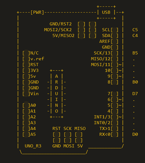
Not exactly schematics, but [Duckman] has some Arduino pinout diagrams he made using ASCII-art. These could be useful when pasted into source code as comments, documenting the pinouts for your project.
Do you recommend any tools for making ASCII schematics, or this just a waste of time?


I haven’t seen ascii schematics since the 90s. That’s some BBS and Newsgroup type shizz.
I was looking at one last night. ¯\_(ツ)_/¯
.---------------------o--------------o---o +1.5V | | | | | | .-. ||100n | .-. | | .----||----. | | | 100k | || | | | |1k '-' | ___ | | | | E | | | | D | | \] | \] | '-----)----|]---------o-----|]-------o B | /]+ | /]+ | l | 10µ .-. 100µ | i | | | | n | | |47Ω V -> k | '-' - e | | | r '---------------o--------------o---o GNDI don’t know if you meant it to be broken, but I fixed it for you…. wrap your ASCII art in
You don’t say what sort of tags to use… more noticeably, the first line gets its proceeding whitespace stripped.
Pre tags. Removes formatting.
https://www.w3schools.com/tags/tag_pre.asp
Text in a pre element
is displayed in a fixed-width
font, and it preserves
both spaces and
line breaks
But in this case the pre tags DID NOT preserve the spaces! I guess we will just add that to the never-ending list of bugs that will never be squashed in WordPress Jetpack. And it’s very likely nobody will ever see this comment because it contains the word Jetpack in it.
Just copied and pasted it. Hence the issues. No idea what types of tags to use. Doesn’t seem to say. You sort of fixed it. Turned LED into ED. Top row is still broken. Looked awful before at least.
+-----+ +----[PWR]-------------------| USB |--+ | +-----+ | | GND/RST2 [ ][ ] | | MOSI2/SCK2 [ ][ ] A5/SCL[ ] | C5 | 5V/MISO2 [ ][ ] A4/SDA[ ] | C4 | AREF[ ] | | GND[ ] | | [ ]N/C SCK/13[ ] | B5 | [ ]IOREF MISO/12[ ] | . | [ ]RST MOSI/11[ ]~| . | [ ]3V3 +---+ 10[ ]~| . | [ ]5v -| A |- 9[ ]~| . | [ ]GND -| R |- 8[ ] | B0 | [ ]GND -| D |- | | [ ]Vin -| U |- 7[ ] | D7 | -| I |- 6[ ]~| . | [ ]A0 -| N |- 5[ ]~| . | [ ]A1 -| O |- 4[ ] | . | [ ]A2 +---+ INT1/3[ ]~| . | [ ]A3 INT0/2[ ] | . | [ ]A4/SDA RST SCK MISO TX>1[ ] | . | [ ]A5/SCL [ ] [ ] [ ] RX<0[ ] | D0 | [ ] [ ] [ ] | | UNO_R3 GND MOSI 5V ____________/ \_______________________/You forgot this…
http://busyducks.com/wp_4_1/2015/11/16/ascii-art-arduino-pinouts/
I have put ASCII Schematic clips in my code to document the circuit I’m interfacing with. (I create embedded code).
Might be OK for small code in boards never to be visited again. But for maintainability? Nuh-uh. You refer to the number and revision, page and sector of the relevant schematic. Single source of information is good.
Given that the code implementation is likely tied to the particular schematic revision, I’d say that this is a pretty good way to make it clear. The information referencing the original doc is still needed, but when that changes, having the abbreviated schematic in the code that applies to it hurts nothing and can help in revision later. In particular when using a versioning system that makes it difficult (or impossible) to access anything other than the current version, or only allows you to see past commits, when the commit may involve changes after the code was written. The real world is a cruel place.
Yes, I have worked under policies that do not allow access to anything prior to the current commit. Policy need not have an obvious reason, or any at all. I’ll bet you can think of as many reasons as I can as to why a large organization might include these restrictions as part of an access and compartmentalization policy.
Heh, I remember a place that had a puzzling quality problem, until they finally found the 7 years out of date drawing taped under the lid of a supervisors desk.
It’s a two pronged thing, the higher ups want tighter distribution control of engineering drawings, so limit distribution, so that the right ppl get the newer revised versions, and they know where old copies are to pull. But then the lower downs, who also need more access to check they’re doing their jobs right, start to regard them as rare and valuable, so sneak copies and hide and hoard them.
I have viewed, and even created many ASCII schematics in the 70’s-90’s. Yes, they’re ugly. But they clearly documented the circuit, and can still be read today.
In the early 1980’s, printers came out that could do custom character graphics. By loading a special font, ASCII schematic printouts were a lot better looking.
In contrast, many CAD programs use proprietary formats. Once the company has moved on to the Next Great Thing, these old schematics often become unviewable.
Well, they aren’t that ugly if special characters are used, too.
In DOS, English code page CP437 was the default (unless changed to CP850 etc) and had plenty of them.
That’s why I used to read plain text files and schematics in Norton Commander (DOS) and not in Windows.
If you’re installing Ansi.sys or a similar TSR, you can even read/view colourful ANSI art in DOS.
At least, if viewed with TYPE on Command.com.
Special ANSI viewers didn’t require Ansi.sys, I suppose.
Same. As a young teen in the early 80s, ASCII schematics were something I knew about. We had a message board system on the university mainframe and I convinced the person who ran it to give me an area to share schematics. Spent hours converting Forrest Mims schems to ASCII.
It would seem any program that can deal with symbols would work. Basically pick and place.
The Parallax Propeller IDE had this feature since the beginning; the Parallax font uses ascii 128-255 for circuit symbols.
https://forums.parallax.com/uploads/attachments/40464/41224.jpg
Yessss… Also the Propeller IDE editor had columnar insert/delete. You can download the Parallax TTF for free here:
https://forums.parallax.com/discussion/84853/parallax-true-type-font
How about MonoDraw?
https://monodraw.helftone.com/
Looks good… but where do I get the source tarball?
If open source is a requirement, you could always write it yourself
Awesime! Thanks for the tip.
This is friggin amazing. All we need now is a kicad output plugin that generates this ;)
That would be an absolutely awesome project!
Are you voulenteering ;) sadly my time is too thinly spread to add this to the list :(
we like this sort of things
WINE/Windows users may also want to try TheDraw:
https://en.wikipedia.org/wiki/TheDraw
What no mention of the Raspberry Pi `pinout` command? Very ASCII. Much pinout.
Maybe in another decade or two folks will (re)discover the standardized block drawing glyphs in Unicode. While ASCII is nice, it can be done properly within Unicode. (Plus it’s retro to go back to the faux windowed text UI’s of the 80’s.)
Fun fact, I once programmed a viewer, that would take ASCII schematics and show them as (Hercules) graphics.
That was so long ago, that I nearly forgot about it.
Was that the Hercules at segment $b800? The VGA card used $a000, so I used the Hercules as a second monitor to run a TSR hypertext-like documentation system. Back when you had to think about the fact that the pixels weren’t square.
i keep detailed journals of every project i do, these days. partly because i’m so scattered lately that a project might sit for years so being able to pick up where i left off is the only way it will ever progress. but also because writing it down helps me think about it.
i just use a flat text file named NOTES (which is always checked into git). so i frequently find myself describing circuits with ascii. it’s part so i can come back to it later, and part as an aid to help me assemble the thing in the first place. a lot of times, i’ve done it by creating basically netlists. sometimes i make a grid to represent perfboard. but the old fashioned ascii schematic actually makes a showing pretty frequently.
i could use a gui pcb cad program but that’s simply not going to happen, and besides, it takes a different kind of discipline to keep a change log with one of those things. i have been known sometimes to draw it on paper and just include a jpeg with the project.
anyways! thanks to mike for pointing out the pre tag works in comments! this schematic is from a failed project, it’s supposed to represent charge level of lipo by how long the LED stays lit, but instead it represents temperature.
I realized I can eliminate Q1 entirely.
Vp —–+—+—+
| | |
C2 R2 LED
| | |
| | R4
| | |
| | D
+—(–G Q3
| | S
C | |
Q2 B–+ |
E | |
| R3 |
| | |
GND —-+—+—+
C2 about 0.1uF (biggest ceramic), if I can get the discharge time right
R2/R3=~10 (I used potentiometer)
Q2 is NPN
Q3 is NFET
R4=1k
LED is little green LED
the rest of that diary is logs of experiments to find the right values for R2 and R3. i go ahead and let the schematic be ugly, but it’s still a million times better than not having it.
hah hah maybe i can’t use pre :)
Ages ago we’d use JavE to make inappropriate images to paste into IRC
http://www.jave.de/
Don’t like it anymore now than then. Only real ASCI/ANSI/EBCDIC art requires a tractor feed 14 7/8 (wide) drum printer and ability not to get caught. It was a firing offense. Like in front of actual firing squad. Worth it to have a life sie Raquel Welch, Spock Holding Enteeprise and of
My version of this was the computer lab and several rasterizer programs that would take in an image and spit out as many pages of free paper and toner you were willing to commit to your dorm room wall. Bonus points if you could find a color printer that didn’t have guns, gates and guards around it
Here are some things to know about AACircuit (v1.28.7, 23.10.2016 at post time): [1] It is a small program, 285KB .zip download, 680KB unpacked. [2] It is a stand-alone application, unpack it and double-click the executable file to run, there’s no installer. [3] AACircuit runs in Wine (at least it did for me the last time I tried, which was awhile back). [4] By default AACircuit runs in German. To change the default language click the Sprache (Language) option and choose in the drop-down list from the following: Deutsch (German), English, Dansk (Danish), or Dutch (Netherlands). Once you have selected your language a pop-up dialog box in German and English will appear telling you that you need to restart the application for the changes to take effect. Click OK to dismiss the dialog box, then stop AACircuit and restart it, now the program will always run in your selected language. Enjoy…