This DIY Split-Flap Display Does Both Time And Weather

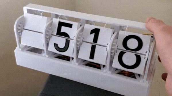
With little more than four economical stepper motors, a Raspberry Pi Zero, and a 3D printer, [Thomas Barlow] made himself an awfully slick Smart Flip Clock that can display not only the time, but also weather data as well. This is done by adding a few extra graphics to some of the split-flaps, so numbers can also be used to indicate temperature and weather conditions succinctly. Displaying the time has to do without a colon (so 5:18 displays as 518), but being able to show temperature and weather conditions more than makes up for it.

32 degrees and a mix of sun and cloud

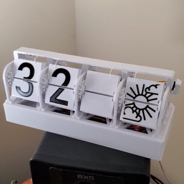
According to the project’s GitHub repository, it looks as though each split-flap has thirteen unique positions. The first ten are for numerals 0 through 9, and the rest are either blank, or used to make up a few different weather icons with different combinations. A Python script runs on the Raspberry Pi and retrieves weather data from OpenWeather, and the GPIO header drives the display via four geared stepper motors and driver boards. The rest of the hardware is 3D printed, and [Thomas] helpfully provides CAD models in STEP format alongside the STL files.

The basic design of a split-flap display is really quite versatile, and enterprising hackers have been putting delightful new twists on them for years. There has been a split-flap display used as a kind of flip-book animation, and we’ve also had the pleasure of seeing an entire Tarot deck used for esoteric, automated readings.

Shipping A CRT: Lessons Learned

Old CRT computer enthusiast [x86VileR] recently tracked down an IBM 5153 monitor for which he had been searching several years. Unfortunately shipping a heavy glass CRT isn’t easy. In fact, it took [VileR] three tries to get a functioning monitor delivered intact and working. The first one seemed reasonably protected in its packaging, but arrived so banged up that the CRT had become dislodged inside the monitor and the neck broke off! The second attempt was packaged even better, and he was sure it would arrive problem-free. Alas, it too arrived all banged up and broken.

This one clearly had superior packaging, so I find it difficult to account for this truly stupendous level of damage. The most promising theory is that several people jumped on it simultaneously, just before the delivery truck ran it over. As my friend put it, it would’ve arrived in better shape if he had just smashed it himself before boxing it up.

Double-boxing appears to be the answer, although it might result in a box too large to ship depending on your courier’s rules. Short of building custom wooden crates, do you have any packing tips for shipping heavy and fragile items? Thanks to [J.R. Dahlman] for sending us the tip.

An Attempt At 3D Printing A Hybrid Rocket Engine

Liquid fuelled engines are throttleable and monstrously powerful, but highly complex. Meanwhile, solid rocket engines are simple and cheap, but once you light them, they’re going full-bore until burnout. Hybrid rocket engines offer perks from both worlds, with simple solid fuel and the ability to throttle down by regulating oxidizer flow. Naturally, [Integza] decided he should try and 3D print one.

The build came about somewhat by accident, as the 3D printed casing of one of [Integza’s] liquid-fuelled rockets continued burning once the fuel was turned off. This prompted the realization that he could 3D print rocket fuel, and simply supply oxygen, creating a hybrid rocket. Thus ensued much experimentation, going so far as to create custom sugar-loaded resin for more power and experimenting with ABS as a potential fuel.

Most of the rockets self-destructed within a few seconds and thrust was minimal, but the basic concept should be a goer. As always, [Integza] is struggling with the thermal limitations of plastics, but we fully expect he’ll one day get to a flight ready engine. His previous experiments show he certainly doesn’t give up. Video after the break.

Continue reading “An Attempt At 3D Printing A Hybrid Rocket Engine”

RGB LED Rings Teach Old Dash New Tricks

We’ve seen several so-called “digital dash” upgrades over the years that either augment, or completely replace, a vehicle’s original dashboard indicators with new displays. Whether its seven segment LEDs or a full-on graphical interface powered by the Raspberry Pi, the end result is the same: a dashboard that looks wildly different than it did when the car rolled off the assembly line.

But this LED dashboard project from [Flyin’ Miata] takes a slightly different approach. Rather than replace the analog gauges entirely, rings of RGB LEDs of the same diameter were placed behind their matte black faces. When the LEDs are off you’d never notice them, but once they kick on, the light is clearly visible through the material.

LEDs can easily shine through the gauge face.

So far, it looks like most of the work seems to have been put into the tachometer. The firmware running on the CAN equipped Adafruit Feather M4 can do things such as light up a dynamic redline based on current engine temperature. It will also light up the LEDs to follow the analog gauge as it moves around, which might not have much practical application, but certainly looks cool.

On the speedometer side, the LEDs seem to be used primarily as warning indicators. As demonstrated in the video below, the whole gauge can light up bright red to indicate a critical situation such as low oil pressure. If you wanted to, the system could also be configured with different colors corresponding to various possible fault conditions.

Compared to some of the more aggressive dashboard updates we’ve seen, this is an interesting compromise that helps retain the look of the original instrumentation. Of course, depending on the make and model of the car, you might be able to sneak in a small LCD screen without anyone noticing.

Continue reading “RGB LED Rings Teach Old Dash New Tricks”

A $50 CNC

In theory, there’s isn’t much to building a CNC machine. Hook a bit to a motor and move the motor around with some lead screws and stepper motors. Easy. But, of course, the devil is in the details. [DAZ] made a nice-looking and inexpensive rig that probably isn’t the most precise CNC in the world, but it looks like it does a good enough job and he claims he spent about $50 on it. The video below shows some of the work it has done, and it doesn’t look bad.

This isn’t a rainy afternoon project. You’ll need to cut some wood and 3D print many parts. The drives use M8 threaded rod. Electronics is just an Arduino running standard software.

The steppers looked pretty light duty, and we wondered if it would have been worthwhile to trade them out for beefier ones instead of modifying the ones used for bipolar operation. Still, the results did look good for $50. The 775 spindle is another place you could probably spend a little more and get something better. Non-printed linear rails, and a better screw? The point is that you’ve got a basis to build from.

Continue reading “A $50 CNC”

Wireless MicroPython Programming With Thonny

I’ve been playing with a few MicroPython projects recently on several different embedded platforms, including a couple of ESP32 WiFi modules. There are various ways to program these modules:

  • Use a serial terminal and ampy (maintained by [devxpy] since being dropped by Adafruit in 2018).
  • If you use Pycom boards or WiFy firmware, there are the pymakr plugins for Atom and Visual Studio.
  • If you prefer the command-line like me, there is rshell by one of the top MicroPython contributors [Dave Hylands].

For over a year, I have been quite happy with rshell until I started working on these wireless nodes. Being lazy, I want to tinker with my ESP32 modules from the sofa, not drag my laptop into the kitchen or balcony to plug up a USB cable. Can’t I work with them wirelessly?

Well, you can use WebREPL. While its functional, it just didn’t strike my fancy for some reason. [Elliot] mentioned in a recent podcast that he’s using telnet to access his wireless nodes, but he’s using esp-link on an ESP8266, which means throwing another chip into the mix.

The Thonny IDE

I had all but given up when by chance I saw this video on the Dronebot Workshop channel about running MicroPython on the new Raspberry Pi Pico boards. Bill was using Thonny, a Python IDE that is popular in the education community. Thonny was introduced in 2015 by Aivar Annamaa of the University of Tartu in Estonia. Thonny was designed to address common issues observed during six years of teaching Python programming classes to beginners. If you read about the project and its development, you’ll see that he’s put a lot of effort into making Thonny, and it shows.

Leaning about Thonny got me curious, and after a little digging I discovered that it has WebREPL support for MicroPython right out-of-the-box. Although this is a new feature and classified as experimental, I found it reasonably stable to use and more than adequate for home lab use. Continue reading “Wireless MicroPython Programming With Thonny”

ASCII Schematic Diagrams

We wondered recently about those crude ASCII schematics you see in some documentation — are there any dedicated schematic-focused tools to draw them, or are they just hand-crafted using various ASCII-art drawing tools? To our surprise, there is such a tool. It is called AACircuit and was developed by [Andreas Weber]. It has a history going back to 2001 when it was first introduced as ASCIIPaint. Be forewarned, however, the quality of the code may be questionable. According to the notes on [Andy]’s GitHub repository:

WARNING: a lot of spaghetti code ahead

This code was created in 2001-2004 when I taught Borland Delphi 3 to myself. It contains many, many global variables, unstructured and undocumented procedural code and bad variable names.

If you don’t want to wrestle with old and sketchy object-oriented Pascal code, you’re in luck. [Chaos Ordered] has made a Pythonized version which you can get from his GitHub repository. We tried it out and got it working on Ubuntu in short order (after wrestling with a pycairo dependencies). This might not be everyone’s cup of tea, but it has some uses now and then. While we wouldn’t want to document a computer motherboard with ASCII schematics, it’s great for a quick-and-dirty circuit diagrams.

Not exactly schematics, but [Duckman] has some Arduino pinout diagrams he made using ASCII-art. These could be useful when pasted into source code as comments, documenting the pinouts for your project.

Do you recommend any tools for making ASCII schematics, or this just a waste of time?