Who wouldn’t want an autonomous drone to deliver cans of fizzy drink fresh from the fridge? [Alex Toussaint] did, and in thinking how such a machine might work he embarked on a path that eventually led him to create a fully functional ultrasonic 3D scanner. In writing it up he’s produced a straightforward description of how the system works, which should also be of interest to anyone curious about phased array radar. He starts with an easy-to-understand explanation of the principle behind phased array beam forming, and there follows his journey into electronics as he uses this ambitious project to learn the art from scratch. That he succeeded is testament to his ability as well as his sheer tenacity.
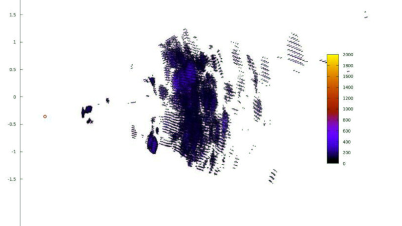
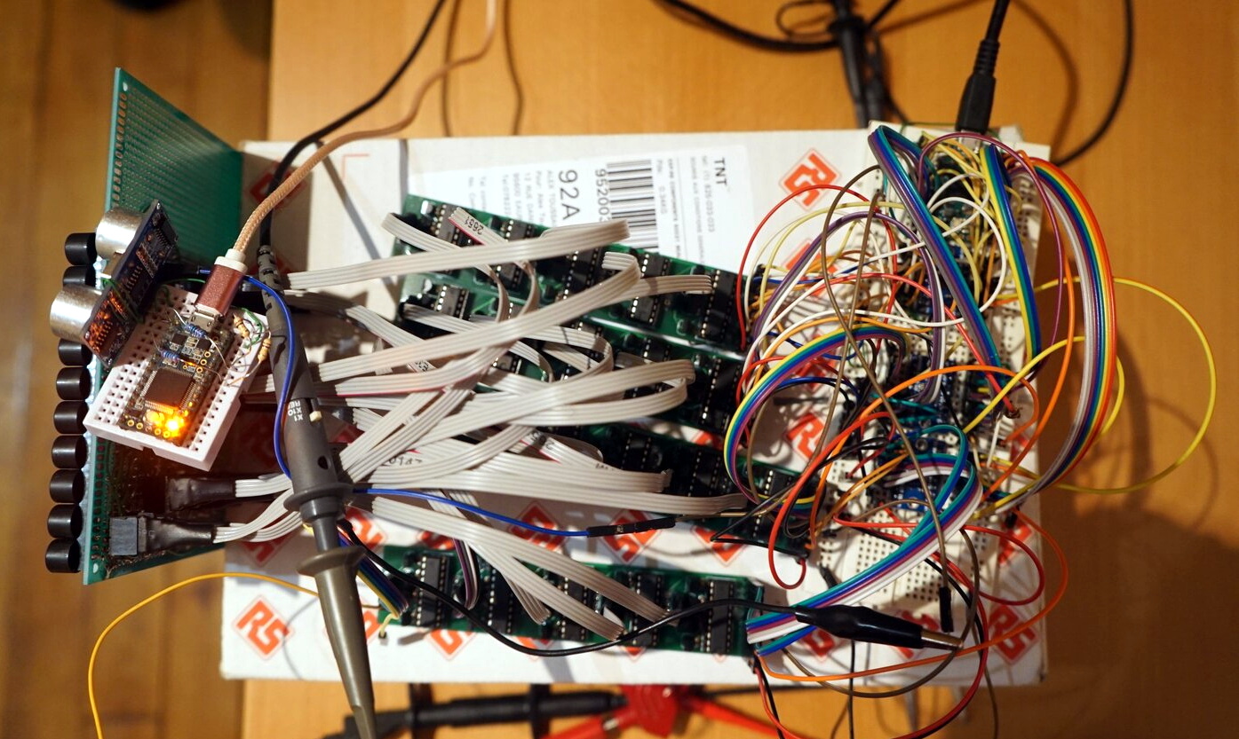 He finally arrived at a grid of 100 ultrasonic emitters controlled from an Arduino through a series of shift register boards. Using this he can steer his ultrasonic beam horizontally as well as vertically, and receive echoes from objects in three-dimensional space. The ornamental bird example he uses for his scanning tests doesn’t quite emerge in startling clarity, but it is still clear that an object of its size and rough shape is visible enough for the drone in his original idea to detect it. If you would like to experiment with the same techniques and array then all the resources can be found in a GitHub repository, meanwhile we’re still impressed with the progress from relative electronics novice to this. We hope the ideas within it will be developed further.
We’ve seen ultrasonic arrays before, but mainly used in levitation experiments.


I think this is really neat. Phased array with sound seems like it should be a lot more attainable by hobbyists. Always wanted to give this a try some day. Hopefully there will be something open source for everyone to tinker with.
Fully functional and electronically correct! Mr Data!
Its always interesting to see how someone else’s perspective can give a completely different take on the same problem. For example, my thought process on the whole thing was 1/4 wavelength spacing simplifies the phased array calculations, what is 1/4 wavelength at 40KHz, and the answer is, of course, it depends, and of course, this led me down a path of removing the uncertainty. I never even got to thinking of the size of the transducers, or dealing with the issues there. He actually doesn’t even mention dealing with the speed of sound in his writeup. I suspect in the code there are some shortcuts obscuring things, and the language barrier isn’t helping to make that obvious. I didn’t try to interpret too much, but it may be that he’s using a hard coded 340m/s for the speed of sound? That would be a little on the chilly side at 15 degrees C (59 F) (at “standard atmospheric conditions”), so perhaps that’s not it. I only did a quick scan looking for a number close to the speed of sound :)
Regardless, there’s no mention of it in the writeup, and no mention of hardware to calibrate it, and since he didn’t get stuck on the issue, he either just assumed some external calibration and he’d make a way to plug it into the software, and he moved on, which is pretty cool because he then encountered another issue. Would I have done the same? No idea, probably not. I’d have probably gone down the path of trying to get/make/find/etc smaller transducers. So again, really cool, different perspective, different approach, etc.
In reality, the speed of sound issue isn’t hard to overcome. In my mind though, I always wanted a purely sonic system, or at most, an atmospheric sensing system combined with a sonic system. The idea of corrupting the system with a speed of light based sensor felt like cheating, like I am missing something, like there has to be a better way…in reality, given how cheap single element radars are these days for distances on par with ultrasonic sensing, I shouldn’t feel this way.
Then again, multielement phased array 60GHz radars can be hacked on the cheap, and there was at least one on a crowdfunding page, so perhaps light speed based phased arrays with large arrays will be available to the masses soonish :) the hack in question is using widi devices, iirc its a 5×4 array. The crowdfunded one I believe is a 5×5 array. 1/4 the elements of this ultrasonic system, but perhaps we will have 10×10 systems in the nearish future :)
Fascinating project. I don’t think speed of sound matters much for the array. At 40khz in your application 1/4 wave is around 2.2mm for any reasonable temperature – speed of sound depends only on temperature of the air in all practicality. So 1/4 wave is unreasonable given he transducer sizes. But as the array gets more elements the spacing restraints get looser and looser. In fact if your hardware can do the math, unequal spacing has advantages. Look at radio telescope arrays. Anyway, you could auto-calibrate easily.
After a little (too little likely) think on this, the “issue” is in the Rx department. If the Tx transducers are also receivers, the reolution can go much higher. In fact, a single Xmit element and an Rx array will do as well or better. There must be a reciprocity relation so “better” would have to come from greater signal/noise when you use a directed beam.
Little bursts of 40khz might correlate well with the received signal and get sub-millimeter resolution. A chirp would be much better but that is always the tough nut. Where can you get affordable ultrasonics with high bandwidth? Waaay back in the late 1970’s I got some samples of a new Piezo Polymer that could do it but the high voltage drive was a real pain to get into a small space back then. (My goal was synthetic low cost aperture SONAR, which cast $20,000+ at the time.) I wonder if there are much better yet affordable transducers than these ceramics. Some of the polymer transducers were shaped like these ceramics but broadband. https://www.steminc.com/PZT/en/piezo-cylinder
Author here, you’re right!
Though, spacing restraints are still valid even with a lot of elements. It’s just that if you don’t respect spacing restraints, you’re going to have many beams at the same time. Which, with a very directional antenna like a parabolic dish only translates in a narrow FOV. But when doing radio astronomy, you don’t care about the FOV (you only need a few seconds of arc of FOV to see a planet) which is why they don’t care that much about antenna spacing. But for a wide-fov scanner, it is still necessary.
You’re also right about the RX. I did TX beam-forming because it was easier for me to build than RX beam-forming (digital electronics is easier to miniaturize than analog electronics) but you’d get exactly the same performance out of a one-emitter and 100 receivers sonar.
Currently I’m not at the level of precision that’s needed to care about chirps and correlations. And even if I was, chirps/phase shift modulations are very hard to implement with piezos (phase shifts are invisible at the reception, and the bandwidth of the transducers is very narrow).
When I had my transducer spacing issues, I looked into making my own transducers but didn’t find much on the subject. Is the tooling needed too expensive? What makes it so hard to build transducers?
For the variable spacing I was thinking of synthetic aperture and interferometry methods where you can suppress the aliasing (multiple beams) and the deconvolution process can give arbitrarily high resolution.