[P1kachu] owns a pair of early 1990’s Honda’s with custom tuning on their stock ECUs, and after having to get the ECU repaired on his ’93 civic, he found himself going down the rabbit hole of Honda ECU EPROM chips.
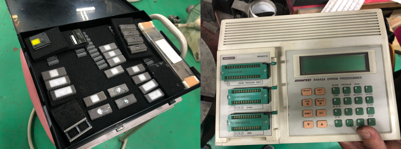
During the repair process, the tuning shop owner, or [Tuner-san] as [P1ikachu] refers to him, made a backup of the custom tuning to another EPROM chip. This was done with an old Advantest R4945A EPROM programmer, which [Tuner-san] supposedly also used to clone Famicom cartridges back in the day. After realizing that [Tuner-san] could only clone the contents, but not view or modify it, he started looking at ways to do that.
EPROMS are programmed using higher voltage (12.5 V – 25 V) but to read them 5 V is used. The memory address is selected by setting each of the 15 address pins high or low, and then reading the status of the 8 data pins to extract one byte of data. Rinse and repeat for each of the 256 memory addresses on the Microchip 27C256 EPROM. One of the previous owners of [Pikachu]’s Civic made some unknown tuning changes, so he is in the process of looking at the dumped data to see what was changed. Once he has completed figuring out the programming table of the EPROM, he plans to do some testing with [Tuner-san] to possible smooth out the rev limited.
An interesting aspect of EPROMs is that they are erased using UV light, which sets all the memory bits to 1. During programming, selected bits can be set to 0, but it’s not possible to set them back to 1 without erasing the entire chip again.
Messing around with the computers in cars is not only for tuning, but can also expose some rather serious security flaws, especially in modern vehicles.


“for each of the 256 memory addresses on the Microchip 27C256 EPROM”.
There are 32k memory addresses. The 256 in the chip number refers to 256*k* bits = 32k bytes.
Where ‘K’ means 2**10 i.e. 1024, plain and simple, which confused exactly no one in the time before the internet. So that’s 32768 addresses in that chip, to be exact.
“After realizing that [Tuner-san] could only clone the contents, but not view or modify it, he started looking at ways to do that.”
The simplest and quickest would be to read the manual for the programmer. It can clone EPROMs, it’s got a hex keypad and a display – it’s going to be able to edit the contents…
And indeed it can: http://thangtien-vn.com.vn/tailieu/R4945A_ope_e.pdf
The text doesn’t say that the programmer cannot do it, only that the person using the programmer is unable. ;)
:) very true.
[Tuner-san] says, “what.eva. I do what I want!”
In my experience RTFM isn’t in most people’s SOP.
Just reading through the Arduino code on the github and they are setting the address and immediately reading the data from the data lines.
(ref: https://github.com/P1kachu/honda-p30-analysis/blob/main/27c256-rom-reader/27c256-rom-reader.ino#L153 )
From the datasheet for a 27C256-20 the “Address to Output Delay” has a maximum of 200 ns. So I would have added a “delayMicroseconds(1);” between setting the address and reading the data lines. I guess that there is enough inherent delay within the program already (by calling a separate function to read the data lines, the CPU registers would all need to be dumped and eventually restored from the stack) and that the code is probably running on slow enough Arduino hardware not to need the addition of a 1000 ns delay.
You are correct in general but, as you noted, it’s probably not a problem here. The Arduino’s ATMega 2560 runs at 16 MHz or 62.5 ns per instruction. 200 ns is a little over three instructions so as long as there’s four instructions in between setting the address and reading the data, the access is within spec. I suspect digitalWrite() requires way more than four instructions.
You can also get an official Arduino Due which is clocked at 84MHz. Or you can even shoehorn an ESP32 board clocked at 160Mhz or 240Mhz to accept code from the Arduino Software IDE.
84MHz would be ~12 ns per clock cycle
160MHz would be 6.25 ns per clock cycle
240MHz would be ~4 ns per clock cycle
When you publish Arduino code, you have no idea what hardware someone will eventually end up run it on.
Am I missing something here? The EPROM programmer has a serial port on the back. Just download the dump to a hex editor, do the changes and upload to the programmer again. Also it’s not a 256 byte chip. It’s a 32k chip.
His cable didn’t fit… You couldn’t make it up.
a TL866 clone costs 5 bucks, so…
AHH I get it!
This to boost our ego, showing how the arduino culture has ruined our electronics education framework, it was a lot simpler before, harder to get to that first blinking led, but a breeze afterwards.
And yes it could be done with a 555, heck I’ve read an eprom with switches and leds just for the kick.(3 or 4 adresses, then it got boring)
I would like to order 1000 of $5 TL866 clones from you sir, where is the address of your webshop?
ok, its more like 30~40 but it also writes them and many more devices so I still stand by my comment.
Plus that scene has long ago migrated to RTP with battery backed srams and flash devices.
So, I won’t be able to buy a $5 TL866 from you?
Money isn’t everything. No offense, but people that think like you are the ones that age quickly. Please don’t become a grumpy old ham, for your own sake. Enjoy life, keep your inner child alive and continue to play around with stuff, even if it’s a little waste of money. ^^ ❤️ vy73/55
I’m just pointing that If the goal was to modify the maps (that’s not firmware hacking BTW), he had much better and simpler options, and probably hackaday worthy anyway.
[P1ikachu] wants to create the tuning software himself, from what i understand. I was in the tuning business for a long while and back in the 90s there were actually GUI software that made the tuning process real easy
Though not every mechanic could use them properly and plenty of them (for costs vs risks) used pre-loaded tunes on the cars , the chiptuning industry is broad