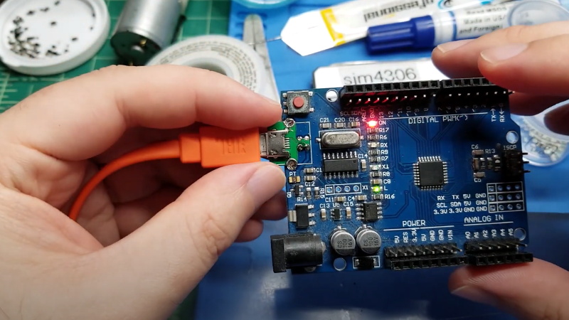
Even with more and more devices making the leap to USB-C, the Arduino Uno still proudly sports a comparatively ancient Type-B port. It wouldn’t be a stretch to say that many Hackaday readers only keep one of these cables around because they’ve still got an Uno or two they need to plug in occasionally.
Looking to at least move things in the right direction, [sjm4306] recently set out to create a simple board that would let him mount a micro USB connector in place of the Uno’s original Type-B. Naturally there are no components on the PCB, it simply adapts the original through-hole footprint to the tight grouping of surface mount pads necessary to mount a female micro USB port.
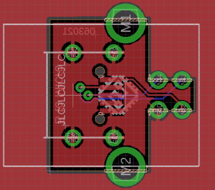
The design is straightforward, but as [sjm4306] explains in the video below, there’s actually more going on here than you might think. Looking to avoid the premium he’d pay to have the board house do castellated holes, he cheated the system a bit by having the board outline go right through the center of the standard pads.
Under a microscope, you can see the downside of this approach. Some of the holes got pretty tore up as the bit routed out the edges of the board, with a few of them so bad [sjm4306] mentions there might not be enough of the pad left to actually use. But while they may not be terribly attractive, most of them were serviceable. To be safe, he says anyone looking to use his trick with their own designs should order more boards than they think they’ll actually need.
Of course you could go all the way and retrofit the Uno with a USB-C port, as we’ve seen done with devices in the past. But the latest-and-greatest USB interface can be a bit fiddly, especially with DIY gadgets, so we can’t blame him for going with the more reliable approach.


Why bother with micro, should have went USBC
“Of course you could go all the way and retrofit the Uno with a USB-C port, as we’ve seen done with devices in the past. But the latest-and-greatest USB interface can be a bit fiddly, especially with DIY gadgets, so we can’t blame him for going with the more reliable approach.”
Last line of the article……
But if you want less fiddly and reliable then just leave the usb b
All my USB B cables are still working. Finger crossed as they aren’t as easily available these days. Can’t say the same for the other type.
My only real annoyance with B is I only use it for this one board and nothing else. Well that and the cable has a habit of disappearing, but I always have a micro cable on hand for charging multiple device I have in my backpack. Sometimes the best tool is the one you can find quickly and easily replace not the one you have to dig around for.
This. In about 25 years I don’t think I’ve ever had a USB A-B cable fail.
I’ve had maybe 1-2 lightning cable fail (despite them being the ones I use most, and the fails were cheap knockoffs), 1-2 mini (though they might have been cheap power only cables), and I’ve had at least 6-8 USB micro cables fail.
Thankfully no USB-C have failed yet. Seems to me like they got the reliability back on C.
Seems to me that as advancements come along, boards should move in the same direction, however, as there is as much room on Uno’s as there is, they could possibly include more than just one USB port. Another option would simply be to have adaptors to fit which ever USB is desired or needed, or across the complete form factor for USB. So it might cost a little more to manufacture, but one either spends that extra for cables, or adaptors or the assembled board with enough port styles to use each of them. Just my thought.
It seems like the largest application for USB B connectors are printers.
Are there any companies making USB 2.0 USB-C connectors? You can find plenty of power only but I dont want to implement 25 fiddly little pins. I need 4 ( maybe 6) pins to hook up the D+ D- and power pins. But they dont exist. And USB micro is nearly everywhere. So we still use USB-MicroB.
Adafruit sell USB 2 connectors in type C format (product 4458), but they’ve 12 pins: because USB C is reversible everything is duplicated. I’ve not seen a connector where the two D+ are internally connected etc.
I disagree with that statement about usb c being fiddly. micro usb is notorious for turning into a hotdog down a hallway. there is even a footprint for making the actually PCB a USB C connector, just make sure to order the PCB in the correct thickness
USB C requires a few more parts in addition to C port. A C port that only has pins for USB 2.0 would be a bit easier to solder than a full C port. I’ve looked into a small drop in board to replace legacy B port on Arduino and a few other with C ports with USB 2.0 only support.
He could have done it with through hole breakouts or even large SMT pads facing down that lines up with the type B mount holes to avoid castellated holes.
It is a connector, so you would expect quite a bit of shear force. You can improve the strength by using a piece of wire with the through hole version.
@tekkieneet, exactly…
* Problem: Change the Arduino Uno’s ancient USB B Female connector to Micro USB Female. No custom PCBs allowed.
* Solution-1, USD $4.49 total to modify ten Unos ($0.45 each):
1. Unsolder the old USB B Female connector.
2. Glue this [link below] Micro USB Female to DIP PCB down in it’s place.
3. Hand wire the connections.
– HiLetgo 10pcs Micro USB to DIP Adapter 5pin Female Connector B Type PCB Converter pinboard 4.4 out of 5 stars 126 ratings $4.49
https://www.amazon.com/HiLetgo-Adapter-Connector-Converter-pinboard/dp/B07W844N43
* Solution-2, USD $9.25 total to modify one Uno:
I cannot find a single USB B Male to Micro USB Female adapter. I did find these two adapters which will work in series like this: USB B Female <–< USB B Male to USB A Female <– USB A Male to Micro USB Female <– Micro USB Male
– DSYJ DSYJ-01252 USB Type A Female to USB Type B Male Adapter (USB_A_F-USB_B_M) 4.1 out of 5 stars 372 ratings $4.26
https://www.amazon.com/DTOL-Type-Female-Male-Adapter/dp/B000AA2SMS
– USB 2.0 Male to Micro USB Female Connector Adapter (2 Pack) 4.5 out of 5 stars 364 ratings $4.99
https://www.amazon.com/Micro-Female-Converter-Adapter-2Pack/dp/B07SDB7XY1
It coule be interesting to try adding small drilled non plated holes right on the routing path where the bit is tearing the copper plating. The holes, if drilled before the routing, would remove the copper first so that no tearing happens when the routine is done.
That’s a good idea, I’ll have to try it next time
Most places don’t allow overlaping holes like that, as drill bits don’t really work when there’s not material fully arround it. They deflect sideways, and can brake off.
One thing that might help a little though is to modify the footprint to have the surface part of the pad shrink to having no anular ring thickness right where the cut happens. It wouldn’t get rid of copper in the hole, but would get rid of the copper on the surface.
Don’t know how much that would change the results though.
Fair point, I didn’t think about the bit flexing. If you use a bit large enough it wouldn’t be a problem though but the pcb fab house would probably not let you try…
I wonder if KiCad let you modify plated holes anular ring in the way tout suggest?
Wondering why the design doesn’t simply route the board outline *outside* the desired holes as is usual practice (rather than routing through the middle of them).
Any half-decent solder job will wick solder down through the top board hole and into the bottom board hole. The only requirement: the boards have to be lined up properly before soldering (actually, the same as with the current ‘half-hole’ design anyway).
Stronger, and brings your PCB ‘failure’ rate down to practically zero.
I agree that in this project castellated holes aren’t strictly necessary, however it is interesting as an experiment to try to produce things that looks like it on the cheap.
I’m with you on trying it for experimentation. The world would be very boring indeed if nobody ever tried experimenting ‘just to see what happens’.
now he’s got a pile of adaptor boards so that he doesn’t have to have a single usb peripheral cable
You do realize I dont take all the adapter boards to work one by one right lol. All this does is allow me to use the same cable my headphones, logic analyzer, mouse, keyboard, pocket oscilloscope, bluetooth speaker, etc use already.
Nice work on the PCB design but IMO it’s a downgrade. USB type B is super secure and durable. If you don’t plan on unplugging often or need low profile it would work great then
That’s fair, this was more of an experiment anyway as I’m not sure how the castellated smd pads will hold up long term. I may have to redesign to use small solid core wire for mechanical strength if it becomes an issue. In the end I plan on making a different version for each usb type so anyone can use whatever standard they find most useful.
Maybe make it underside mountable, using the B pins as both mechanical and electrical connection, you get a choice of either
+1
“move things in the right direction”
No thanks, I choose durability any day. Never have I had more broken connectors than with microUSB and USB-C.
The micro is already very weak physical connector and making it protrude like that is making it more weak.
i just glued a micro-USB (on a board from Banggood) to the side of the USB-B and ran some wires …
Why on earth would you replace a good and reliable connector by the most crappy one ever made!?!?
This.
I can insert USB-B all day and it will work as on the first day, can’t say that about micro USB.
Well done! 🙂
But if miniaturization is a thing, why not use Mini-USB? 😕 My old USB card reader uses that, never had a problem with it! IMHO, both USB-B and Mini-USB have an easily to recognize shape (visually). Inserting them is thus much more fool-proof than it is with USB-A.
If you look hard enough you can find pretty much convert USB from anything to anything else adapters either with cable length or just a one piece.
Bit less permanent.
I found a micro to mini to plug my DSLR into my phone for example.
Also got a to mini converter plugged into the back of my scope which is inexplicably USB A.
Micro-USB is pathetic junk.
Solved that issue a long time ago with adapter like this “USB C Female to USB Type B”.
https://www.aliexpress.com/item/1005002805440175.html?spm=a2g0o.productlist.0.0.364ba56a4eVXEf&algo_pvid=3d45e4d0-2c00-4ec5-8079-0d020e4f1ea5&algo_exp_id=3d45e4d0-2c00-4ec5-8079-0d020e4f1ea5-17&pdp_ext_f=%7B%22sku_id%22%3A%2212000022269642949%22%7D
Some of the Arduino clones have a micro-USB socket already. My favourite is the “Eleven” from Freetronics: https://www.freetronics.com.au/products/eleven It also has some other nice features that you don’t get on the cheap clones.
The PCB in the article is a nice hack though. Interesting pseudo castellated holes. I’ve used similar PCB daughterboards to raise sockets off the “main” PCB so the sockets all line up neatly.
Is it possible to buy some of these adapters?