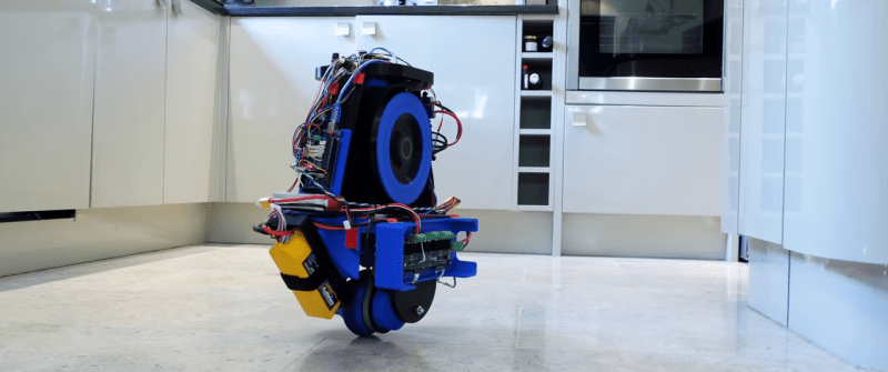
Self-balancing robots have become a common hobby project, and they usually require two wheels to work. [James Bruton] has managed to single wheel balancing robot by adding gyroscopic stabilization.
[James] has done other self-balancing robots, like his Sonic robot, but recently started experimenting with gyroscopic stabilization. In that project, he proposed the idea of combining the two stabilization methods to create a monowheel robot, and he followed through on that idea. The wheel is powered by a brushless motor and is stabilized conventionally around the wheel’s axis. Side to side balancing is achieved using a phenomenon known as gyroscopic precession, by tilting a pair of heavy spinning wheels. This is not to be confused with reaction wheels, which use rotational inertia for control. It appears the actuating the gyroscopes also affects the front-to-back stabilization, so at the moment the robots won’t stay on one spot. [James] plans to implement a second observation controller in software to solve this.
Another challenge with this robot is that it cannot turn at the moment. The gyroscopes are not in the correct orientation to effect rotation around the vertical axis, and changing their orientation would cause other problems. A fan, which works like a helicopter’s tail rotor is one option, and a reaction wheel on top might also work. We’re partial to the reaction wheel idea. Having a different mechanical control mechanism for each axis would make it quite an interesting robot.


Hop and turn?
What about a castor wheel? Bit of a stretch maybe but can’t be worse than a shopping trolley
It’s a basic law of physics … nothing’s worse than a shopping trolley.
Mm I think shopping trolleys go in the AI section :/
But anyway, re physics I wonder if the robot, using a rounded shoulder tire, could lean over just enough to turn while accelerating and straighten back up. If it start falling over….while turning then increase speed (see centrifugal force). Would be a good size turning circle I’d imagine.
Why do European ones have four swiveling wheels, each at the end of an angled leg, while North American ones have two fixed wheels at the back, two swivel ones at the front, and a wire tray underneath?
Interesting, I did not know that.
In the US, the carts inevitably get dragged when they collect and transport them back from the parking lot to the store, which leads to flat spots on the back wheels. Very annoying and loud. But also one of the casters always drags a little more or gets damaged and the cart will pull to one side or the other, which means you have to constantly correct for it the whole time your shopping or spend a few minutes testing carts before you choose one.
At least you can still keep the cart going in the direction you want. I assume if the european style trollies get “tweaked” or pull one way then the whole cart will go sideways or straffe requiring you to twist your body to correct?
Maybe this helps? How big are the grocery stores in Europe? In the US, they’re massive and arranged in a way where straight movement down long aisles is more desirable vs frequent turns.
https://www.loadmoverinc.com/explanation-wheel-configuration/
As the two gyros are displaced in the X axis, couldn’t you independently turn them (deferentially) to effect a net force to turn the robot on it’s gravity axis?
How do unicycle riders turn? I’d imagine the same principle could be applied here too.
Unicycle riders mostly pivot turn on the spot (wheel) using the difference between momentum and energy, both of which are conserved. So it’s a ratio of a first order (mv) and second order ((m/2)v^2) laws of physics. This is relatively easy to do as the control loop is mostly governed by physics and the rider only needs to input a loosely calculated force.
Alternatively it is possible to use a ratio of two second order laws of physics, gravity and linear forward acceleration (ironically to cause rotation). This however requires the rider to govern a complex second order control input which is difficult to do. Additionally, the smaller the turning radius is the more accurate the control input needs to be as the effect of error increases exponentially. So this method is only used for very large radius turns as the skill required increases exponentially with the reduction of the radius.
Much the same applies with electronic control loops. Although electronics can do much more complex math it may lack in response time. The faster the response the lower the error is at the time of the response and with second order control loops error can increase exponentially towards control failure.
The old timey way to deal with this was to intrinsically link second order elements via physics with other second order elements and link these to a first order element that is used as the control element.
Examples:-
In this project both second order gyro’s are physically linked by the first order control element such that the one control input controls both second order elements at a fixed ratio.
On a (motor|bi)cycle, the front wheel is a second order element (rotational acceleration) used as a ratio to another second order element (gravity). These are controlled by the rider by a first order element (moving left or right or turning the handlebars). This is possible for the rider as most of the second order ratio is fixed by what is called the “rake angle”. This is essentially the distance forward between the control input (handle bars) and the rotational axis of the wheel.
Other good examples are the old timey household power meter. The differential magnetic windings of a newtonian fludic fuel gauge on older cars.
Hopefully this is a bit of fuel for thought for those who bravely think outside of the box of traditional robotics.
With our hips.
Instead of reaction wheels what about a spring-loaded mass inside a channel, aligned laterally and in front of the main wheel axis. A small motor driving a ratchet escapement tensions the spring, and a servo or solenoid to release it when wanting to turn. The mass flies outwards and comes to a sudden stop which would “kick” it around a tiny bit in that direction. One mass and channel required for port and starboard. The masses could be lead slugs or chunks of tungsten carbide to keep the volume down. So, in effect, two motor-driven slide hammers.
As the spring is pushing the slug in one direction, its also pushing the robot in the other, and then when the slug stops its moved back to where it started. I don’t think the result would be much of a turn. I think even if you just ejected the slug all together it wouldn’t be enough to overcome the inertia of the robot unless the slug was very heavy and the spring very strong.
I think the reason this might work (on earth, at least) is the piecewise nature of friction. The initial pulling back of the slug creates a force too small to overcome static friction, so no movement occurs at all. Then, the quick movement of the slug back into position overcomes the static friction from the wheel on the ground and the robot turns.
One idea I’ve had but haven’t pursued is putting a spherical magnet inside a set of 3 orthogonal coils. Perhaps in a teflon casing and with some suitable lubrication.
It could be spun in any direction, making both reaction wheel and gyroscope operating modes possible under software control.
This sounds like it has huge potential. The teflon/lubrication sounds like a good POC starting point. In theory you do away with the friction with magnetic suspension ie a magnetic bearing.
I tried this a little bit by 3D printing a sphere studded with magnets, with alternate polarities facing outward. I couldn’t figure out how to make a driver for the orthogonal coils though, so it just sits on my shelf like an abstract geometric sculpture.
Go buy two of those L298N based bipolar motor driver boards. It would be interesting so see how you wound the coils.
Just needs a weight that a servo can shift left or right then as it’s moving forward or backwards it’ll lean slightly and turn.
Gyros should be rotating batteries on slip-rings, they need to be heavy anyway!
I don’t know much about batteries but intuition suggests that many chemistries might not take kindly to being crushed by a centrifuge. I might be completely wrong about this though.