Gyroscope Walks The Tightrope

Gyroscopes are one of those physics phenomena that are a means to many ends, but can also enjoyed as a fascinating object in their own right. Case and point being [Hyperspace Pirate]’s tightrope-balancing crawler in the video after the break.

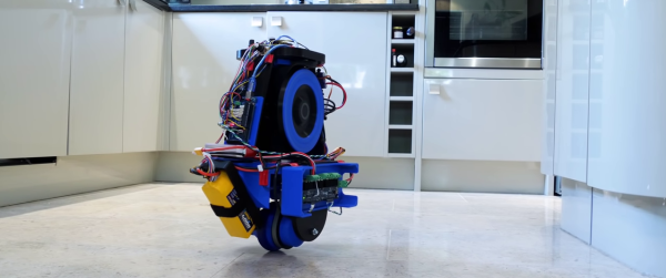
Inside the PLA and aluminum shell is a 3D-printed wheel with steel bolts around the edge for added moment of inertia. It is powered by a low-KV brushless motor with a 3:1 GT2 belt-drive and controlled by a simple servo tester, running on a 4 cell LiPo battery. The 3D-printed drive wheel is powered by a geared DC motor hooked directly to the battery. [Hyperspace Pirate] goes over the math of the design, showing that path to stability is a high speed and high moment of inertia flywheel, while staying well within the strength limits of the wheel’s material.

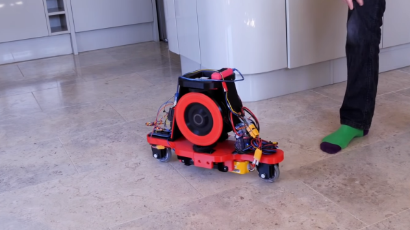
It’s balancing act was first demonstrated on a length of PVC conduit and then on a section of rope, with the characteristic circular wobbling of a gyroscope, known as gyroscopic precession. Without active correction, this the angle of procession will steadily increase until the machine falls over. Even so, it’s still great to watch a small scale version, like the one that inspired this build, would make a pretty cool desk toy.

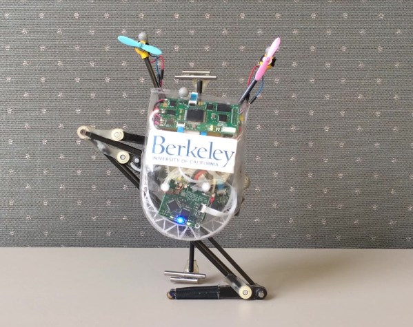
Gyroscopes are commonly used in attitude indicators and and heading indicators in aircraft, and we’ve also seen them get used for balancing robots. Any ideas for practical uses for a mono-wheel rail/rope walker? Drop them in the comments below.

Continue reading “Gyroscope Walks The Tightrope”

Monowheel Balancing Robot Can’t Turn (Yet)

Self-balancing robots have become a common hobby project, and they usually require two wheels to work. [James Bruton] has managed to single wheel balancing robot by adding gyroscopic stabilization.

[James] has done other self-balancing robots, like his Sonic robot, but recently started experimenting with gyroscopic stabilization. In that project, he proposed the idea of combining the two stabilization methods to create a monowheel robot, and he followed through on that idea. The wheel is powered by a brushless motor and is stabilized conventionally around the wheel’s axis. Side to side balancing is achieved using a phenomenon known as gyroscopic precession, by tilting a pair of heavy spinning wheels. This is not to be confused with reaction wheels, which use rotational inertia for control. It appears the actuating the gyroscopes also affects the front-to-back stabilization, so at the moment the robots won’t stay on one spot. [James] plans to implement a second observation controller in software to solve this.

Another challenge with this robot is that it cannot turn at the moment. The gyroscopes are not in the correct orientation to effect rotation around the vertical axis, and changing their orientation would cause other problems. A fan, which works like a helicopter’s tail rotor is one option, and a reaction wheel on top might also work. We’re partial to the reaction wheel idea. Having a different mechanical control mechanism for each axis would make it quite an interesting robot.

Continue reading “Monowheel Balancing Robot Can’t Turn (Yet)”

Rover Uses Different Kind Of Tracks

Tracked robots usually require at least two wheels inside to work properly. However, [James Bruton] discovered a curious tractor design from the 1940s, the Fordson Rotaped, which only uses a single sprocket wheel inside each track. Being [James], he built a self-balancing robot around the rotaped concept.

Instead of a lot of short track sections, the Rotaped uses six long sections of track, about the same length as the wheel’s diameter. To keep the track on the wheel, a series of chains or an oval frame is used on the inside of the track.

As is usual for [James]’ projects, most of the mechanical parts are 3D printed. To hold the tracks in place, he stretches a bungee cord loop around three points on each side of the track. To make things more interesting, he made the robot balanced on the tracks. This took a bit of PID tuning to get working without oscillations, since the wheels experience a slight cogging effect inside the tracks. The wheels are driven by a pair of brushless motors with O-Drive controllers. The balancing is handled by an Arduino Mega, which reads processed position values from an Arduino Pro Mini connected to an MPU6050 IMU.

This might be a viable alternative to conventional tracks for certain applications, and the reduced part count is certainly an advantage. Let us know in the comments if it spawns any ideas. [James] has previously built another tracked rover, which uses flexible 3D printed track sections. By far, the biggest 3D printed tracked vehicle we’ve seen was [Ivan Miranda]’s ridable tank.

Continue reading “Rover Uses Different Kind Of Tracks”

Actively Balancing A Robot With A Gyroscope

Self-balancing robots are a common hacker project, but we don’t often see them using spinning gyroscopes to achieve that balance. Robot master [James Bruton] decided to build a robotic platform with active gyroscopic stabilization, starting from a simple proof of concept.

A gyroscope can balance, but cannot actively counteract external forces directly. However, if the gyroscope is tilted around an axis it will exert a force perpendicular to that axis of tilt, known as gyroscopic precession. By tilting the gyroscope with an actuator, and orienting the gyroscope correctly, gyroscopic precession can be used for stabilization. This is known as a control moment gyroscope. [James] demonstrated this with a 3D printed proof of concept, which is used as an IMU to measure the angle of tilt, and use a PID loop to correct the imbalance with a servo actuating the gyroscope.

His second platform used a pair of gyroscopes spinning in opposite directions to compensate for any unintended gyroscopic precession along another axis. A pair of roller skate wheels allow the entire platform to roll along. Due to a slight imbalance in the platform, [James] noticed that the gyroscopes will continue to creep in one direction, until reaching the end-stops and falling over. By adding a second software controller to keep track of how much the gyroscopes have to move to maintain balance, it can continuously calculate and update the balancing point. This prevents the gyroscopes from hitting the end stops.

Control moment gyroscopes are commonly used for attitude control on spacecraft, and to reduce the rolling motion of boats in waves. [James] has plans to combine a control moment gyroscope with the more conventional balancing method, to balance a robot on a single wheel.

We’ve seen a two wheeled RC cars use gyroscopes before, but without the active control part.
Continue reading “Actively Balancing A Robot With A Gyroscope”

Ultra-Mobile Little Robot Will Climb The Walls

Can it crawl? Can it climb? Can it roll? Can it skate? Can it draw? Naminukas by [Mykolas Juraitis] can do all of those things, and it is the size of a winter boot. Roving robots generally fall into one locomotion category, and the fanciest are amphibious. We categorize this one as transforming between three modes.

The first mode is like an inch-worm and a robot arm. Using a vacuum cup at the hub of each wheel, it sticks one end to the ground then heaves itself in the direction it wants to go and repeats. Its second form is a two-wheel balancing robot, which is the fastest configuration, and it can even carry things on its suckers. For the finale, it can hybridize all the tricks and use a camera dolly like a skateboard. One end sticks to the dolly, and the other is a propulsion wheel.

Naminukas is not just about scooting around the floor, because it can use tools with enough dexterity to write legibly on a whiteboard, climb walls, and even move around the ceiling. If these become sentient, there will be no place to hide, except a room with shag carpet, and is that any way to live?

We enjoy multi-terrain vehicles from soaring seaplanes to tidal tanks.

Continue reading “Ultra-Mobile Little Robot Will Climb The Walls”

Little Jumping Bot Can Now Stick The Perfect Landing

Sticking the perfect landing can take years of practice for a human gymnast, and it seems the same is true for little monopedal jumping robots. Salto-1P, an old acquaintance here on Hackaday, always needed to keep jumping to stay upright. With some clever control software improvements, it can now land reliably on an area the size of a coin, and then stay there. (Video after the break)

[Justin Yim] from the UC Berkeley’s Biomimetics Lab has been working on Salto for the past four years, and we’ve covered it twice before. Attitude control is handles by a combination of propeller thrusters for roll and yaw, and a reaction wheel for pitch.While it was already impressive before, it had a predictable landing area about the size of a dinner plate.

The trick to the perfect landing is a combination of landing angle, angular velocity and angular momentum. Salto can only correct for ±2.3° of landing angle error, because it doesn’t have a second foot to catch itself when something goes wrong. Ideally the robot’s angular velocity and momentum should be as close as possible to 0 at takeoff, which gives the reaction wheel maximum control authority in flight, as well as on landing.  Basically a well executed takeoff directly influences the chances of a good landing.  [Justin] does an excellent job explaining all this and more on the project’s presentation video. Continue reading “Little Jumping Bot Can Now Stick The Perfect Landing”

Self balancing robot

Building A Self-Balancing Robot Made Easy

Not only has [Joop Brokking] built an easy to make balancing robot but he’s produced an excellent set of plans and software for anyone else who wants to make one too. Self-balancers are a milestone in your robot building life. They stand on two-wheels, using a PID control loop to actuate the two motors using data from some type of Inertial Measurement Unit (IMU). It sounds simple, but when starting from scratch there’s a lot of choices to be made and a lot of traps to fall into. [Joop’s] video explains the basic principles and covers the reasons he’s done things the way he has — all the advice you’d be looking for when building one of your own.

He chose steppers over cheaper DC motors because this delivers precision and avoids issues when the battery voltage drops. His software includes a program for getting a calibration value for the IMU. He also shows how to set the drive current for the stepper controllers. And he does all this clearly, and at a pace that’s neither too fast, nor too slow. His video is definitely worth checking out below.

Continue reading “Building A Self-Balancing Robot Made Easy”