For conventional vertical takeoff and landing rotors on vertical shafts are the most common solution, as seen in helicopters and multirotors. A much less popular solution is the cyclocopter, which consists of a pair of rotors spinning around a horizontal shaft with horizontal blades. [Nicholas Rehm] built a remote-controlled cyclocopter as part of a research project and gave us an excellent overview of this unique craft in the video after the break.
Also known as the cyclogyro, the idea is not new, with the first one constructed in 1909. The first flight was a long time later in the 1930s, but it was quickly discovered that they were too unstable to be flown manually by a human, so the idea was shelved. Thanks to modern microcontrollers, researchers have recently been able to build small-scale versions, like the tiny example from the University of Texas.
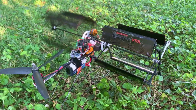
Lift is produced using four or more airfoils on each of the two cycloidal rotors. At the top and bottom of rotation they have a positive angle of attack, with a neutral angle on the sides. The blades’ angle of attack can be adjusted to produce forward or reverse thrust. An additional motor with a conventional propeller is mounted on the nose to counteract the torque created by the main rotors, similar to a helicopter’s tail rotor.
Unlike multirotors, cyclocopters don’t need to pitch forward to move horizontally. The blades also don’t need to be tapered and twisted like a conventional rotorcraft, since the relative airflow velocity remains constant along the length of the blade. However, they have some significant downsides that will likely prevent them from moving beyond the experimental stage for the foreseeable future. The rotors are quite complex mechanically and need to be very lightweight since the design doesn’t lend itself to great structural strength. This was demonstrated by [Nicholas] when a minor crash snapped one of the rotor arms. However, it is an excellent demonstration of the adaptability of [Nicholas]’ open-source dRehmFlight flight controller, which he has also used to fly a VTOL F-35 and belly-flopping starship.
Would you be surprised that this isn’t our first cyclocopter hack?


Absolutely awesome!
This technique was adapted to a vertical axis windmill in the early 1980s. The Pinson Cycloturbine worked pretty well but the complexity of the mechanical movements didn’t make for commercial success. The position of the blades was controlled by a weather vane on top of the machine. Herman Dreese, the inventor, later moved to California, working on one of the large windfarms there. I worked on some of the controls and instrumentation with Natural Power and later worked on another windfarm in the Altamont Pass.
It might yield a smoother ride if instead of airfoils, they used a rotating cylinder. It would be more efficient and be less twist sensitive.
That dry ice demo at the start makes me think there’s little to no downdraft coming off this, compared to the massive blowing force that comes off even small vertical propellers. This could be extremely useful is some niche situations where downdraft needs to be avoided. Close-in filming comes to mind, and I wonder if this would be less disturbing to wildlife below.
My next question would be if the design scales the way multi-rotor systems do? With vertical propellers you can keep slapping more rotors on and the lifting force scales linearly (not counting the additional weight of power delivery, batteries, etc.) or switch to larger propellers on stronger, faster motors for more lift. Does lift in this design scale as linearly with additional cyclo-wing assemblies, or larger ones with more powerful motors?
The downdraft from flying vehicles of all types at a stationary elevation is purely dependent on their weight. That is actually the true mechanism for lift, pushing air down. It doesn’t matter if it comes from rotary blades or fix wings moving through the air. Both cause a pressure differential that drives air down and creates upward force for lift. The reason you think helicopters generate more downdraft is because airplanes can’t hover in one spot. If you flew under another airplane, you would experience constant downdraft. It will be the same for this vehicle.
I wonder just how accurate it is to state, “That is actually the true mechanism for lift, pushing air down.” I was always under the impression that flight occurs because of the pressure differential with higher pressure below a wing compared to above the wing resulting in lift. I wonder what would happen if airplane wings had the ability to vacuum/suction air above themselves and then force air out the tail. Would that not result in lift/flight without downdraft? Also, I suspect blimps and helium balloons “fly“ without a downdraft.
Fly’s, and doubles as a wheat thresher. :-P
I wonder if you could do away with the tail rotor by adding another two cycloidal rotors at the back and counter-rotate them. As lift and direction of travel aren’t determined by the direction of rotation this should be viable.
Oops, already been done.
https://youtu.be/VEP4KYqkF4k
Flipping cool man!
Very cool! But I had to laugh when he suggests the cyclorotor’s simpler blade geometry is more attractive than traditional helicopter blades. That may be true if you ignore the massively increased complexity in powering and controlling them and decrease in structural robustness. Absolutely not taking anything away from the design, you often learn more making something impractical work than simply replicating a proven design.
I wonder if a cyclorotor has any ability to autorotate in case of a power failure.
It would be interesting to build one where the rotational speed is a set rpm, varying the positional inclination of the blades and the amount of deflection for the blade set. My thoughts go to a variable displacement mechanism of an engine or variable lift on valve position.
That’s pretty much how helicopters control their lift. It’s called collective pitch on a helicopter, and is controlled via a swashplate. I guess on a cyclocopter it would still be called collective pitch but it should be controlled by a swash cam.
Looking through some videos on youtube, most of these designs look to use a fixed pitch, similar to the smaller toy helicopters without collective, varying rpm for verticle control. Looking at the contol method on the cyclocopter, i would imagine 3 concentric control shaft/tubes. Pitch, direction and the rotating drive shaft. The xam would be intersting mechanism… on each end of the rotor groups…. nothing to go wrong there…
Is this design vulnerable to vortex ring state?
Can you make a wind power generator using this tech?
Im with Igo can one generate electricity with this same technology?
Possibly naive question: could pitch stability be achieved by having with one pair of counter-rotating rotors?
Hi Danie, Beautiful project. Very well done. You mentioned an interest in new projects. I have two cycloturbine windmills that are quite unique. They use different types of passive pitch control. They are simple to build, but difficult to understand because they use new principles. One is exceptionally efficient, and the other is exceptionally inexpensive. You might enjoy building one or both of them. I can send you my papers that explain how they work.
Hi Peterz I am planning on building a Cyclorotor drone and wood love to see your plans.