[Martin] sent this query, along with the lead photo, into the tip line, and he makes a good point. Most development and evaluation boards have multiple rows of pin headers, often arriving loose in the package — soldering is left to the user. In an abundance of caution, we usually design our prototype boards with many pin headers for debugging and testing. But as [Martin] reminds us, there are other alternatives to solder.
- Yours truly once worked with a prolific designer of PIC microprocessor boards. Long before the advent of solutions like the Tag Connect family, [Ralph] would program his boards by just inserting a pin header into the PCB and applying gentle pressure with his thumb until the code finished flashing.
- You may have seen the staggered offset PCB patterns that hold your pin header securely while you solder. You could tweak this a little bit to put more pressure on the pins, making a solder-less connection that is sufficient for temporary testing.
- Taking the opposite approach, you can get solderless connectors with press-fit pins, a method we tested a few years ago on a Raspberry Pi Zero. Anyone who has worked on Eurocard-based systems like VME can appreciate the time-savings and improved reliability of 96-pin DIN-41612 press-fit connectors.
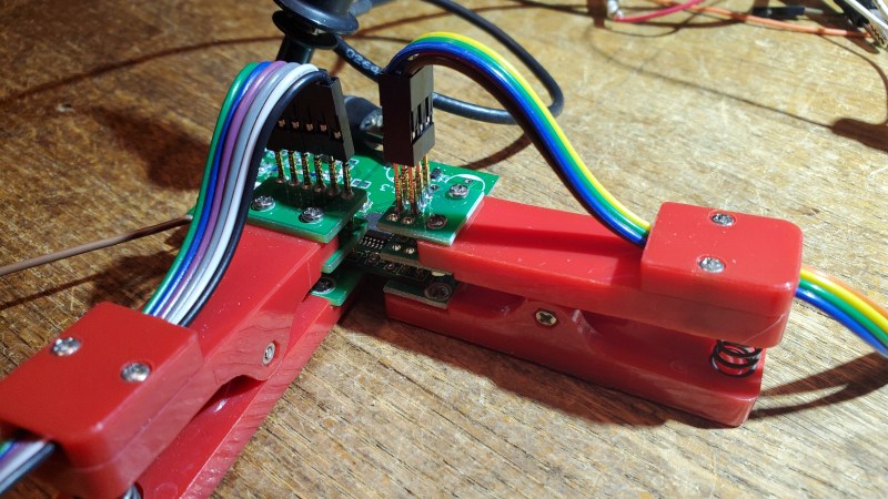
- Or, as [Martin] proposes, you could use one of these inexpensive pogo-pin clamps. These are available for less than $10 from your favorite Asian electronics distributor. They are about the size of a large clothespin, and are available in several different pin configurations.


These techniques won’t help you if you need to plug your board into another card, such as a hat onto a Raspberry Pi. But when you just want to grab a few signals for a serial port or probing some digital I/O signals, having a few of these clips in your tool box can save you the time and headache of soldering down a header. Do you have any tips for making soldering pin headers easier, or even avoiding them altogether? Let us know in the comments below.


Very Nice. I need this in my life
I don’t think I have any pin header cables and always solder wires directly into the holes where the pin headers are supposed to go.
I remembered from ages ago working on boards with press-fit backplane connectors (quite reliable too) so I did a quick search on mouser and you can also get press-fit headers e.g. the Amphenol BPH7B10H00LF is 10 way 2 row 0.1″ pitch.
You probably aren’t supposed to use them twice, but….
If someone has a new STANDARD low-cost way to connect to all the desired IO and signals on an eval board… I’m open to it. but right now, 0.1″ headers are the best for this tinkerer, when it comes to microcontrollers. Of course, if you’re not doing much with hardware (eg a wifi or ethernet board) you won’t need much. Maybe just a standardised connector or bus for I2C etc?
Also, if soldering a 0.1″ header is a headache, perhaps a different hobby would be advisable. ;-)
yeah that’s just what i was thinking…i love 0.1″ headers. super easy to solder, easy to put an ic clip test lead on. big enough you can see what you’re doing and you can usually mark the pins of interest using sharpie or nail polish on the board or on the plastic base. you can shove em in a breadboard. just all around a super convenient technology for my purposes.
the only reason i’d skip the header is if i need to fit it into a tiny case at the end, in which case i have had decent luck (ymmv) using ic clip leads directly on the thru holes in the pcb. but really, when i’m prototyping i don’t usually care that much about the size and i’m definitely not above cutting off the test wires to save space if i wind up using the prototype electronics in the final box.
Reasons: cost, space.
1) For a commercial product, the cost of the headers and mounting them add up. And that makes your product undesirable compared with the one that costs 10c less.
2) I’ve done plenty of designs where 0.1″ headers for debug/programming would take up more space (volume) than the rest of the circuit!
Not all people have the same abilities. Perhaps a different perspective would be advisable.
While that may be true enough, there is also the basic skillsets involved with the hobby… Electronics has *Always* been a hobby or even a profession that requires certain skillsets and the ability to apply solder to a circuit to make connections has always been at the forefront.
Now there *have* been things like wire-wrapping and screw connector adapters to lessen or eliminate the need for soldering but those come at the cost of space and sometimes still requiring soldering or paying more for the option of screw terminals. I am sorry if this bothers you but it is a fact of life and “different perspectives” are not usually viable without a tradeoff in some other way. Perhaps a more “advisable” perspective is to realize that there are some people are just not going to be able to do some things without certain abilities.
I guess I don’t really understand how soldering on pin headers is a headache, it takes me less than 1 minute to cleanly do a 40 pin row. Maybe it’s because I do it often? I can see this being useful for flashing things that are normally in low profile enclosures though.
Sometimes testing and prototyping without solder is a good idea and more flexible. I just ordered a bunch of the clothespin types on Aliexpress. And you know that if you use your last header, that board is going to blow up.
This is my favourite method to solder 40-pin headers (bonus points for the “The sponge has to die” sequence at the end).
https://www.youtube.com/watch?v=i9pd9sY0Tjg
(Might have been featured here some years ago.)
Holly f*ck that is nice video! Thanks.
Your friend Ralph’s way of doing things is very common.
As stated by others, 0.1″ pitch headers are hard to beat. 2mm ones are (for now) evil…
How about a teeny tiny card edge
A piece of perfboard will keep the pins in alignment and in place when soldering. Especially if you are using multiple headers in one row.
Clever! If I’m soldering a male header strip, I’ll mate it with a female header while soldering to keep the pins straight when they heat up.
This is really a good habit for just about any type of connector. I do it with everything from pin headers to big XT90 power connectors. Nothing worse than dealing with a partially melted connector for the rest of that device’s life.
I really like TagConnect footprint, but always found the cost a little prohibitive, so I created this design at a fraction of the cost: https://hackaday.io/project/171391-tagless-programmer
I really should post the files.
I loaded the files at the link for anyone who wants to build one.
Interesting, thanks for sharing !
> […] inexpensive pogo-pin clamps. These are available for less than $10 from your favorite Asian electronics distributor.
Or maybe support the original creators, Tag-Connect for just $20 more?
Seriously, they’re like $35. I get it, it’s not quite $10, but it’s a reusable tool. Plus the OG one is gonna be more reliable and have support. AND they’re gonna give you a footprint they’ve already properly vetted.
https://www.tag-connect.com/product/tc2030-idc-10-6-pin-tag-connect-plug-of-nails-spring-pin-cable-with-ribbon-connector-10-version
The inexpensive pogo pin clamps are in the first image and use the 0.1″ pin spacing of linear headers. They don’t use a unique footprint or really require support. TagConnect is useful if you don’t have the room for 0.1″ headers.
It seems like there are few designs for how to connect to rows of header pads, but what would be a good design of ‘header pad’, if we assumed we’d never actually solder in headers, but always use pogo pins, etc? Perhaps castellated, to still allow soldering modules to carrier boards etc?
The “lock” footprints were developed by Spark Fun.
It’s a wonder to me how some people argue so hard against using it, citing some crazy reasons, including all the “extra” effort of laying out circuit boards using this design (selecting one footprint instead of another). One member in a popular forum made such a fool of himself arguing about these footprints rat he was banned for a month. Bless his heart
Yes, I CAN solder a standard 0.1″ header, but it’s far easier when a lock footprint is used. I seem to recall my boss preaching about working smarter, not harder.
https://www.sparkfun.com/tutorials/114
That’s a good idea, and probably the pins will be in contact – all of them – so you can put a quick header in for programming or debug and then remove it with no soldering required.
I just bought a PCBite kit for probing test points, as an alternative to soldering headers on flying leads to every board. It’s essentially a set of pogo pins on goosenecks.
They’re not cheap, and the probe handles are pretty big, which makes it difficult to probe signals that are close together, but otherwise it works really well. Looks really fancy, too!
I was happy with http://protofusion.org/wordpress/2013/05/open-hardware-pogo-pin-programmer/ for a project that included dozens of prototype boards. But you’re back to square one if you misplace your pogo board.
Have been using Tag-Connect on all my board, independent on architecture, for years. Well worth the money.
Alternative 1. Pogopins, super cheap. And, if you want to make a test jig for your board, copy the board design and add a 1mm hole everywhere you want a testpoint, then mount pogopins on those holes and route the tracks to a suitable connector.
A very useful alternative 2:
If you have relatively low # of pins, up to about 4 pins in line, or 2×3, make holes for a 2mm connector.
A standard 0.1″ male will then match perfectly in the holes, with good retention due to the slightly angled pins.
Pinheads need pin headers.
Maybe you can try to use the double row Pogo pin connector .
like this one.
https://www.pogo-pins.com/products/629.html
hope can help you.
andy