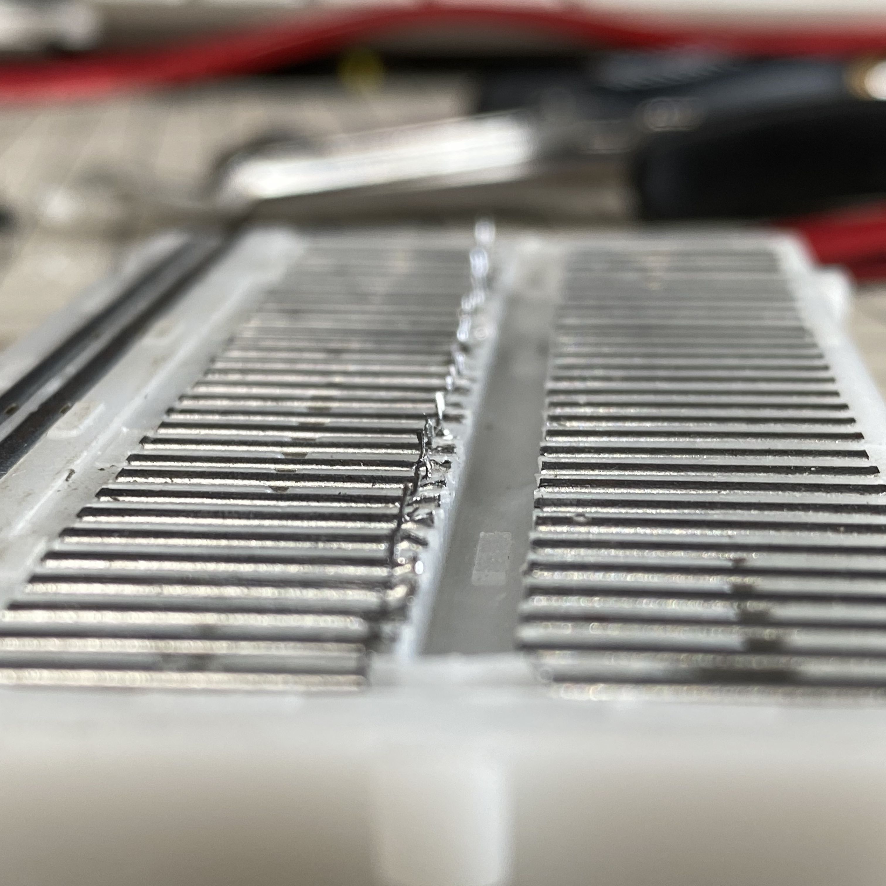
Solderless breadboards are a fantastic tool for stirring the creative juices. In a few seconds, you can go from idea to prototype without ever touching the soldering iron. Unfortunately, the downside to this is that projects tend to expand to occupy all the available space on the breadboard, and the bench surrounding the project universally ends up cluttered with power supplies, meters, jumpers, and parts you’ve swapped in and out of the circuit.
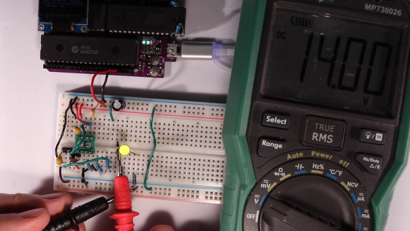
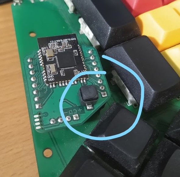
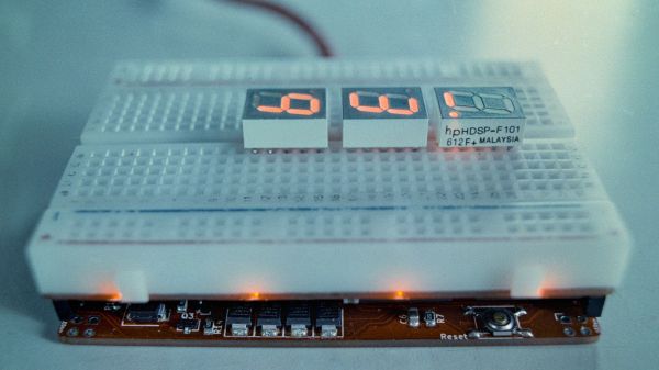
In an attempt to tame this runaway mess, [Raph] came up with this neat modular breadboard system. It hearkens back to the all-in-one prototyping systems we greatly coveted when the whole concept of solderless breadboards was new and correspondingly unaffordable. Even today, combination breadboard and power supply systems command a pretty penny, so rolling your own might make good financial sense. [Raph] made his system modular, with 3D-printed frames that lock together using clever dovetail slots. The prototyping area snaps to an instrumentation panel, which includes two different power supplies and a digital volt-amp meter. This helps keep the bench clean since you don’t need to string leads all over the place. The separate bin for organizing jumpers and tidbits that snaps into the frame is a nice touch, too.
Want to roll your own? Not a problem, as [Raph] has thoughtfully made all the build files available. What’s more, they’re parametric so you can customize them to the breadboards you already have. The only suggestion we have would be that making this compatible with [Zack Freedman]’s Gridfinity system might be kind of cool, too.