Afterburners are commonly agreed to be the coolest feature of military fighter aircraft. Injecting raw fuel into the exhaust stream of a jet engine, afterburners are responsible for that red-hot flaming exhaust and the key to many aircraft achieving supersonic flight. [Integza] wanted to see if the same concept could be applied to an electric ducted fan, and set out to find out.
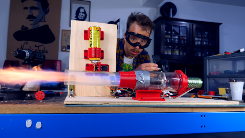
Of course, building an afterburner for an EDF does add a lot of complication. A flame tube was installed downstream of the EDF, fitted with a brass tube drilled carefully to act as a fuel injector. The flame tube was also fitted with an automotive glow plug in order to ignite the fuel, which was lighter refill gas straight from a can. The whole assembly is wrapped up inside a clear acrylic tube that allows one to easily see what’s happening inside with the combustion.
Results were mixed. While the fuel did combust, but in a rather intermittent fashion. In proper operation, an afterburner would run with smooth, continuous, roaring combustion. Additionally, no thrust measurements were taken and the assembly barely shook the desk.
Thus, if anything, the video serves more as a guide of how to burn a lot of lighter gas with the help of an electric fan. The concept does has merit, and we’ve seen past attempts, too, but we’d love to see a proper set up with thrust readings with and without the afterburner to see that it’s actually creating some useful thrust. Video after the break.


He built a Reddy Heater
My Reddy Heater broke, the fan basically disintegrated. I since got a new fan, but in the interim I used a leaf blower pointed in the back to run it. Maybe try a leaf blower fan?
Leaf blower? The suction would skew the forward travel of him & his backpack, or whatever he mounts it to… Probably a tethered mock witch flying in circles for halloween, at first, unless his wife has her license to fly. Well, the side torque will be ok for this. It will have to be a bif battery and invertor though or the cord will get twisted in a, uh, hot minute.
Looks like our man could do with a bit more of a solid grounding in thermodynamics. This is just some burning fuel in a pipe, not a jet engine.
While his EDF afterburner does look a little under-analyzed, he wasn’t trying to make a turbojet.
“Our Man” has built an actual jet engine, so go jump in a lake. And he did a scratch build, not salvaging a turbo from the junkyard like most people.
That doesn’t change the fact that burning fuel at close-to-ambient pressure, in fast-moving air, doesn’t generate any additional thrust – fuel needs to be burnt upstream of a nozzle, at higher-than-ambient pressure (like most heat engines, compress then add heat), to get anything useful from it (even from a statics perspective, if this was producing additional thrust, where would the force actually be transferred to the engine? Pressure differences can’t push straight walls streamwise)
It ends up being close to Rayleigh flow (https://en.wikipedia.org/wiki/Rayleigh_flow), where impulse function ~ thrust-per-unit-mass-flow doesn’t change
I remember dreaming of making something like this before I learnt thermodynamics though, still a cool build!
(and not too hard to modify to be effective – fan>diffuser>burner>nozzle would make the fuel burn at higher static pressure than ambient pressure, and actually generate some extra thrust – but then the nozzle is redirecting hot gas and probably needs to be made out of something more resistant to melting/softening)
All correct, but he should still see a modest increase in thrust in this rig, because the heated (and therefore less dense) exhaust is moving faster than if it were unheated. If the intake fan can keep up the mass flow against the resulting backpressure, the output airstream will have more momentum when heated than when unheated.
Double the temperature (300K > 600K) you’ll get half the air density, so it has to move twice as fast to get the same mass flow, so you get twice the momentum (thrust), *if* the mass flow remains the same (which requires more power from the intake fan).
Though it’s really silly: All you’re really doing is forcing the increase in the power output of the intake fan. You could get the same effect without the flaming shenanigans, just by turning up the motor current.
True, well spotted! Or by adding a convergent nozzle with half the area after the fan, to get twice the velocity for the same mass flow (which should generate the same pressure at the fan exit as the doubled temperature if I’m thinking right?)
Yeah, an appropriate size nozzle will do the same thing.
It’s really an impedance matching problem, just like a car transmission or bicycle derailleur or lever or a transformer.
There’s usually some method to keep the the thrust boundary away from combustion (fan) chamber. I think this runs rough and produces little thrust because the afterburner injection is producing force that negates the fan output.
Funny, I went through that calculation last winter, thinking about converting my leafblower into a snowmelter (for winter) and bicycle power assist (for summer), by adding an afterburner just like this.
The leafblower generates about 40N of thrust all by itself.
The best I could possibly do without catastrophically melting something would get me around 200N of thrust, raising the temperature of the exhaust to 1200C.
It would drink 1.5 liters per minute of gasoline, generating close to a megawatt of heat.
Would make a fine snow (and asphalt) melter, but not terribly efficient for bicycle power assist.
Makes me wonder how much fuel Colin Furze’s pulsejet bike drank.
ISTR his pulsejet bike used one of those standard 5kg propane tanks for each run of maybe a few minutes (they use liquid propane). So the answer is basically “all of it”.
“You see, on a turbojet engine you don’t really use a normal fan to suck air in, you use a centrifugal fan.”
A fair number of early turbojets did this, and at least one modern one (he PW-600 is the only one I’m finding), and it looks like a lot of drone-sized <10kg do as well, likely due to the fact that you can get a good amount of compression from one stage. However, every afterburning turbojet and low-bypass turbofan that I can think of are axial flow, along with almost every commercial turbofan. It's simply more aerodynamically efficient as you aren't shoving the air around corners as you are with a radial compressor.
For an EDF, I don't see any reason to go radial, as energy spent on pressurization is lost if you aren't relying on charge compression for efficient combustion (even disregarding the aero losses of the centrifugal fan). You want exit static pressure as close to ambient as possible (otherwise the energy you've put into the air is wasted in directions other than straight back).
Don’t the axial flow jets rely on the air being supersonic at some point and a shock wave barrier that acts like a one-way wall? I have no idea about the centrifugal ones. They always struck me as kinda crazy in an airplane. OK for a ground power system I suppose but they must be very inefficient.
I don’t remember the proper name for the one way wall but I think that’s a big issue in this project. make explosion go out back, not front
Nope, you don’t need supersonic flow for an axial compressor to work – the most intuitive explanation I can think of is:
axial velocity/axial stagnation pressure is conserved between rotors and stators, but the relative swirl velocity isn’t (because rotors are spinning)
if each rotor/stator takes its inlet relative swirl velocity, and turns/redirects the flow towards being axial (relative to itself), there’s a gain in axial velocity, which can then be slowed down to add static pressure
Mathematically you start looking at rothalpy (stagnation enthalpy in a rotating reference frame), and flow angles in different reference frames instead, but the equations still drop out that you can get pressure rises without any near-sonic stuff
The flow doesn’t go backwards because, in the reference frame of each compressor blade, the stagnation pressure isn’t changing along the blade (or is decreasing slightly along it from viscous effects) – the stagnation pressure increase only really appears with the change of reference frame – no shockwaves necessary
Practical compressors do have supersonic flow sometimes, but that’s mostly to get the power density higher and make the engine lighter-for-the-same-power – there’s a drop in efficiency from the shockwaves, but with the same blade angles power scales with density*area*(velocity cubed), so you can make a smaller, lighter engine with the same power by moving the air faster and spinning at more rpms, until it gets too inefficient/loud/dangerous
Centrifugal ones add pressure partly from the transfer between spinning and stationary bits like a stage of an axial compressor, and partly from centrifugal effect (pedantic way of saying centrifugal force) – spinning air would be thrown outwards without external forces, so the air at the outside gains pressure until it balances (so a centrifugal compressor can generate a pressure rise with zero flow, axial can’t). Centrifugals are easier to design badly, because even with no aerodynamic optimisation you still get that pressure rise from centrifugal effect. An efficient centrifugal compressor is hard to design because the flow is very 3-dimensional (so you can’t do experiments along a 2d slice of blade shape to optimise, have to do the whole thing at once), but getting better with CFD. As far as I’m aware, the main drawback of centrifugal compressors is the large frontal area, and the drag you get from having a big solid wheel in the way of the airflow.
Pratt & Whitney JT15, turbofan, which is in every Cessna jet made, I believe, as well as Beech and others. They made a ton of them.
And yeah it’s the pressure differential that makes these so attractive. A centrifugal fan can maintain a pressure ratio of about 2, where an axial fan is more like 1.2… but axial fans are so much easier to stack to get the required numbers.
It’s all about the likes.
Why no thrust measurements taken? Put the contraption on ballraces in channels, or suspend from lines to the corners with the front against a set of scales placed on edge. Even a couple grams of change would be a great thing to crow about – a ‘look, see, it worked!’ sort of thing. And full marks for saying ‘centrifugal’ correctly.
I remember this guy, he has a bunch of videos on printing rocket nozzles. He uses some advanced methods to cool his cylinders similar to rocket engines. He showed one at the beginning of the video where the flow of O2 was circulated around the walls to allow higher temps in the actual jet. Also did some interesting 3d ceramic printing. All are worth watching I think from a hobbyist point of view.
He’s fun to watch, but when he starts running his rocket/jet engines in his ancient attic with very little protection I get very nervous. Somehow I don’t think his homeowners insurance is going to cover that fire. Fortunately he lives in Portugal and has universal health care.
Hot surface ignitor: Watch the video…
For a setup why didn’t he just raid a toaster for glowing metal?
“Our Man” has built an actual jet engine, so go jump in a lake. And he did a scratch build, not salvaging a turbo from the junkyard like most people.
About 10 years ago, before we understood how jet engines worked, we built a similar type of “engine”. Was a nice test bed and V2 worked allot better.
It used a vacuum cleaner motor so that we would control airflow and the very little trust it provided more precisely.
https://www.youtube.com/watch?v=BEjfNuAkAEc
This is all very silly. Far better it were used to cook tomatoes.
I wonder if you could use this setup as a lighter burner for a hot air balloon? (Gotta fly somehow.)
How small can you make an EDF?
I’d like to hook a humidifier up to a Star Wars X-Wing model, having the steam / smoke / spray coming out all 4 engines.
To keep size down, I hope to put a single fan inside the body of the model. Water source and batteries external, in a base mount.
Out of all the Star Wars merchandise, the lack of an X-Wing humidifier is actually a surprise.
They could be possibly in quite all the sizes, as small as you want, as long as we ignore efficiency. There exist motors as small, and with a decent 3d-Printer it should be possible to make a simple smaller edf. Love the idea!