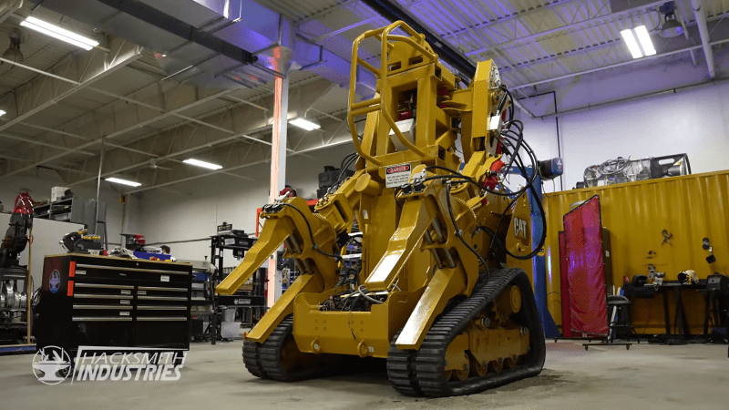
Exoskeletons, power suits, and iron suits in science fiction have served as the inspiration for many engineers and engineering projects over the years. This is certainly the case at [Hacksmith Industries], where Hackaday alum [James Hobson] has been building a massive mechanical exoskeleton since January 2019, inspired by the P-5000 Power Loader from the Alien movies. (Video, embedded below.)
Unlike the movie version, the [Hacksmith] power loader is not bipedal but built on top of the chassis of a small tracked skid-steer loader. Its existing hydraulic power unit also feeds all the upper body hydraulic cylinders. The upper body maintains the basic look of the movie version and was built from plasma-cut steel sections that fit together with a tab and slot system before being welded. Each arm has five degrees of freedom, controlled by proportional hydraulic valves. The power loader is controlled by an industrial grade control system based on the Raspberry Pi, running ROS.
Every single actuator is capable of applying enough force to kill, so safety is an important consideration in the design. It has emergency stop buttons mounted in several locations, including on a wireless remote. The ROS controller monitors the position of every cylinder using string potentiometers for closed-loop control, and to trigger the emergency stop if an actuator goes out of bounds. The power loader can be controlled by the onboard pilot using a pair of simulator flight controller joysticks, or remotely using a PS4 controller.
[Hacksmith Industries] is clear about the fact that they are building multi-ton power loaded for fun and entertainment, not because it’s necessarily practical or a commercially viable product. However, other exoskeletons have proven that they are a viable solution for reducing fatigue and risk of injury for industrial workers, and carrying heavy loads in rough terrain.


Why the huge backlash when moving? Isn’t there negative feedback?
Because they haven’t fitted all the proportional valves yet to replace the valves that are full open or full closed.
I would want to have something a lot less hacky than the string potentiometers for joint position sensing. Should be something built into the joints like a toothed reluctor ring and a hall effect sensor, as is used on the crankshafts of many engines. Those have one tooth missing for the index pulse. I’d put the missing tooth at each joint’s neutral position then on power up have each joint do a little jog back and forth to sense each side of the gap.
The toothed ring with the missing tooth can not distinguish back and forward movement, it can not deliver an absolute position.
There are hydraulic cylinders with position sensors in the rod. I think this works with a magnet in the pistin, magnetostrictive materials in the sensor rod (inside the main piston rod) and traveling ultrasound waves.
Toothed ring could distinguish direction via standard quadrature using two hall sensors at slight angular offset wrt each other
Yup. Home to the center at startup then the software is programmed for each reluctor tooth edge = X degrees rotation, and also programmed for each joint how far the limits are. If one doesn’t fully trust the soft limits, add end stop sensors to *stop* the movement for certain.
Always people like Martin, where if one doesn’t detail how every little thing works, you’re wrong. And if you do detail how every little thing works, they ignore 90% of what’s written to focus on one thing they disagree with, so you’re still “wrong”.
It is really about physics. When you stop a moving load, that cylinder is going to bounce back and forth until the pressure is equal on both sides of the piston. In the direction of movement, the pressure will rapidly rise causing bounce back the other directions and this cycle will continue with smaller and smaller movement like a bouncing ball until the pressure equalizes. Relief valves and cushioning valves help cut the time it takes for this to happen but momentum does not just go away. Position sensing can tell you what is going on but cannot take momentum and pressure out of the equation. The position sensor can say stop but momentum says keep going.
I’ve seen guys operating construction equipment who are artists at smoothness, both hands on the lever sets, carefully adjusting the positions of all of them simultaneously to move a backhoe arm as though it was his own arm holding a scoop. Not a bounce, jerk, or jounce. With proportional electric operated valves it should be possible for a computer to match that performance.
Then there are the machine “operators” that pull one lever at a time, jerking it all the way open then letting it go when the joint gets where the person wants it. They have the entire machine banging and shaking. The mechanics hate those guys because they pound the bearings, pins and cylinders to death. Hydraulic hoses fatigue and pop from all the pressure spikes.
It may have to do with the hydraulic system. Two things come to mind. First, the valves may not be proportional and are either full flow or no flow leading to jerky stops and starts. Secondly on heavy equipment there are often cushioning valves in the cylinders which allow some bleed through to cushion stops. Think of an excavator swinging a very large massive arm. When you let off the movement you don’t want to come up against a solid mass of fluid so they using a spring loader relief valve in the cylinder that allows a very small amount of fluid to past at very high pressure. This prevents the bounce back that occurs when the mass impacts and tries to compress the mostly non-compressible fluid. If you did not have this on a large machine you might have a 20,000 lb arm slamming into a closed hydraulic valve at speed, this would cause a huge pressure spike way over normal system pressure and could damage things.
Hydraulic engineering is difficult stuff. Imagine a system designed for 5,000 psi system pressure and then have an arm pick up a 30,000 lb load. Drop that load at high speed and then let go of the control valve. All of that weight and momentum is transferred to the fluid on the closed side of the cylinder and stopped at the valve. All of that load needs to be considered and relief pressures need to be set balancing the safety of the load and machine against the maximum design pressure of the hydraulic components. A softer relief valve lowers pressure and impacts to the system at the cost of less precise control of the load which itself causes safety concerns.
“It may have to do with the hydraulic system.”
Could have saved yourself all that writing if you’d watched the last couple of videos on the project. They’re changing the valves from simple open/closed types to proportional, and demonstrate with one arm having the open/closed valves and the other with proportional valves.
Proportional is much smoother but they still have more software tuning to do.
I did watch the videos, I just answered the question above (why the huge backlash). I still don’t think it is mostly a software problem. I believe that proportional valving helps but is just a workaround. Proportional valving is just trading speed for a smoother stop (i.e. you ramp up and down your speed at the beginning and end of a move). Proper cylinder sizing and cushioning valves can allow you to keep high acceleration and still smooth out the jerkiness. Another thing done in big hydraulic systems is to use gas accumulators (usually nitrogen or air) to absorb and redistribute the unwanted pressure spikes. They take the pressure spike and use it to compress a gas which can then put power elsewhere in the system or vent it to the atmosphere to dissipate.
I would have gone all electric instead of hydraulic because if you are machining that many parts then you might as well make some motors and avoid the many pitfalls of hydraulic systems… but that’s just me.
It would be nearly impossible to fit the level of performance they want into each of the joints with electric motors, and you would need huge amount more motor and wiring – Hydraulics do have downsides, but they let you take one really big engine and distribute its power very compactly (at the actuator), efficiently (yes there are losses but they are for the forces available actually quite low) – just plain effectively to any number of joints, even a number of joints at the same time..
You only need to account for one big power source, and some slightly bulky valves – which are all often in one central location, with small actuators and simple hose connections vs the really enormous amount of high current carrying wire (much of it having to flex with joints), a truly stonking big battery/ alternate powersource to be able to dump all that current, active cooling for the motors and motor controller, then add in the gear trains needed to make each joint functional for an electric motor, and the actuator/motors themselves as impressive as things like Brushless motors now are are massively more bulky for the power they can deliver…
Could take a page from the injection molding playbook. There are companies that make electric direct replacements for hydraulic cylinders, and they match or exceed the speed and power of the hydraulics.
But their choice of platform already has a powerful hydraulic pump, and I’d bet there’s no electric generator that small with equivalent power capability.
Let us know when it can crack a hazelnut without making it into Nutella!
B^)
How about doing stuff like this, with a raw egg? https://www.youtube.com/watch?v=tr1Wt-PC8fU
These exoskeleton machines first appeared in Stanislaw Lem’s novel “Fiasko”. I think that was what inspired Ridley Scott for “Alien”.
Lem was an impressively imaginative author … he anticipated nanotechnology, swarm intelligence, AI and much more as early as the 1950ies.
I think I drove one of those in a video game once.
Awesome work!
I like how it’s a cross between Guido and a HK-Tank