NFC tags are a frequent target for experimentation, whether simply by using an app on a mobile phone to interrogate or write to tags, by incorporating them in projects by means of an off-the-shelf module, or by designing a project using them from scratch. Yet they’re not always easy to get right, and can often give disappointing results. This article will attempt to demystify what is probably the most likely avenue for an NFC project to have poor performance, the pickup coil antenna in the reader itself.
The tags contain chips that are energised through the RF field that provides enough power for them to start up, at which point they can communicate with a host computer for whatever their purpose is.
“NFC” stands for “Near Field Communication”, in which data can be exchanged between physically proximate devices without their being physically connected. Both reader and tag achieve this through an antenna, which takes the form of a flat coil and a capacitor that together make a resonant tuned circuit. The reader sends out pulses of RF which is maintained once an answer is received from a card, and thus communication can be established until the card is out of the reader’s range.
Very Few NFC Tags And Readers Are On The Same Frequency
For the majority of tags likely to be experimented by Hackaday readers the RF frequency is 13.56 MHz, and the RF emissions are supposed to be in the magnetic field plane rather than the electric field. There’s nothing complex about the antennas, indeed it’s easy enough to make one yourself by winding a suitable coil and tuning it with a small variable capacitor. The RF properties of the antenna can be explored with instruments as simple as a signal generator and an oscilloscope, or if you’re a radio amateur old enough to have picked one up, a dip meter. For the purposes of this article I’m using a NanoVNA because of its extreme convenience, and I’ve set it to measure SWR on port 1 with a sweep between 10 MHz and 20 MHz. I’m loosely coupling it to the NFC antennas I’m testing by means of an RF pickup coil, one turn of wire about 10mm diameter soldered to a coaxial connector and secured with a bit of glue. When I place the pickup coil over an NFC tag, I’m rewarded with a sharp peak on the VNA from infinity down to near 1:1 SWR. This works well with most reader coils and with lower power NFC tags that simply contain a memory chip, but my VNA doesn’t provide enough energy to measure those tags with higher power integrated circuits such as bank cards, a public transport card, or my passport.


Immediately, the VNA pinpoints one of the problems inherent to mass-produced NFCs, that the resonant frequency is rarely exactly on 13.56 MHz. In writing this article I found that both cards and readers appear to resonate anywhere between 13.5 and 15 MHz, with the majority being measured at about 14 MHz. In practice most readers provide more than enough energy so the tag can still be energised despite the resulting inefficiency, but for any NFC tag system to work at maximum efficiency it should have both reader and tag adjusted to resonate at the 13.56MHz frequency of communication.
The Simple But Clever Tech In Your Bank Card
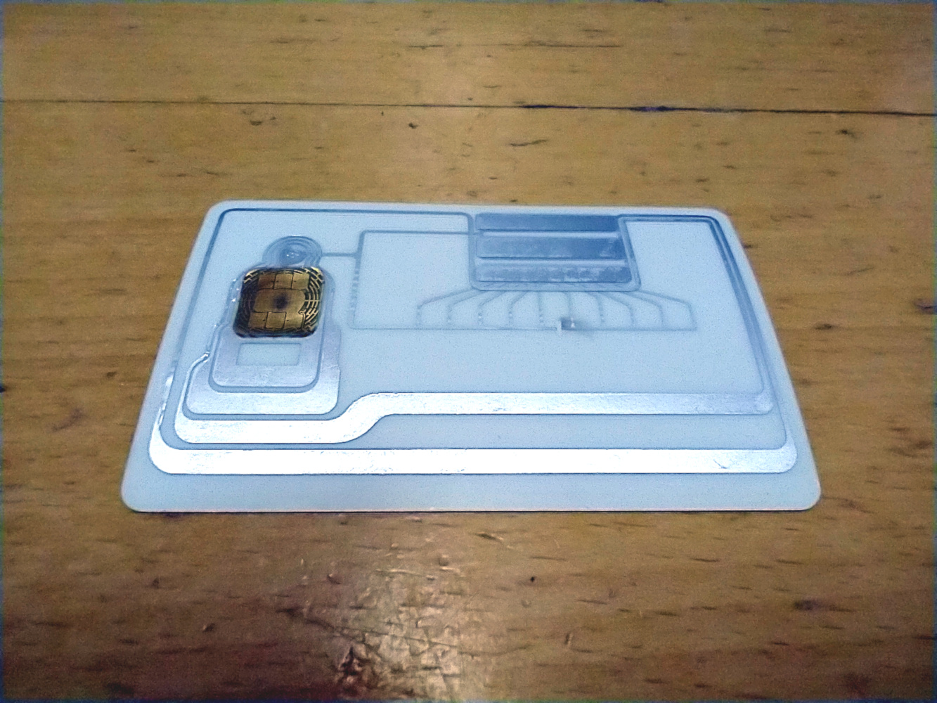
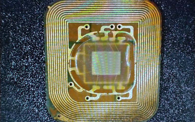
Most tags, and the cheapest reader modules, have very little effort put in to tuning them to resonance, but one of the more interesting tags I examined for this piece, a bank card subjected to a teardown by a hackerspace friend, shows a very clever approach to automated tuning. A bank card is a standard chip card made from two laminated layers of plastic, with the chip contacts appearing in the front face. Upon dismantling it can be seen that the chip and its contacts are on a small piece of plastic about 10 mm by 10 mm that can be lifted clear of the card.
This module can be read by a card reader, but only when it is placed directly on the antenna rather than with any part of the whole card in proximity to the reader as would happen in a shop. To ensure the small chip module can be energised by a reader over the whole surface of the card, the rear half of the card is a printed circuit board that is simply a tuned circuit with a large coil and an ingenious variable capacitor made from a row of small PCB plates. The coil is half-and-half round the edge of the card and closely round the chip, allowing it to pick up the field over a large area and couple the resulting energy closely into the chip. It’s tuned during manufacture by cutting a trace connecting the capacitors, at a guess this will be an automated process. Measuring its resonance it turns out to be a little higher than 13.56 MHz, but since that measurement was made on a dismantled card with no chip in place it’s likely that the resonant point will have been moved upwards.
Tuning An NFC Reader For Maximum Smoke
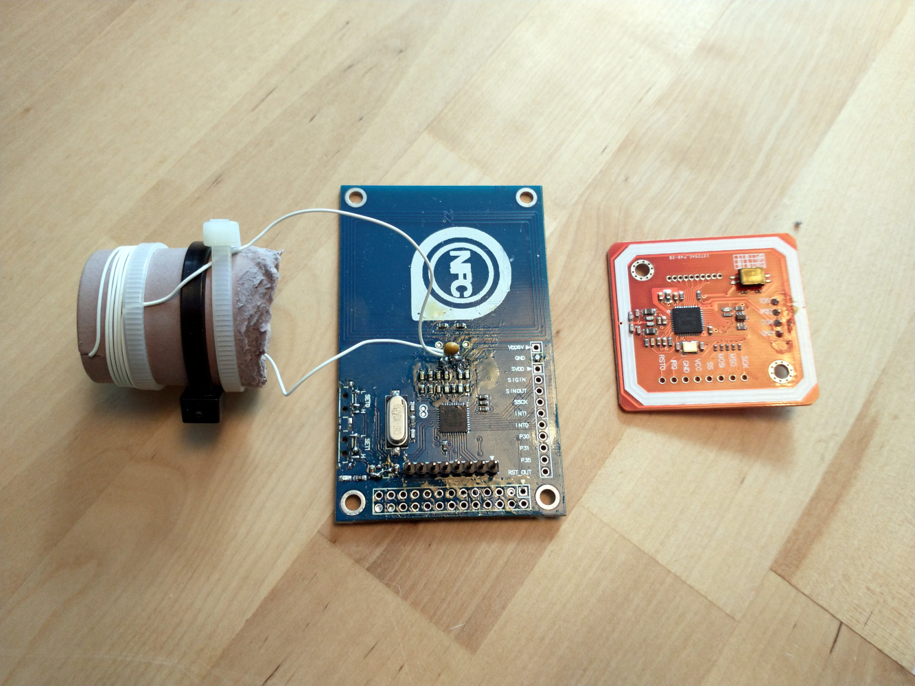
Turning to the readers, the more expensive devices have a built-in variable capacitor and will have been factory-tuned to 13.56 MHz, while the cheap modules normally have a fixed capacitor and resonate at a higher frequency. Experience with these cheaper modules suggests that they will usually interact with the simpler cards such as the ubiquitous MiFare Classic, but that they are unable to provide enough energy to power the smarter cards such as the MiFare DESfire tags. Adjusting the antenna on the module for resonance at 13.56 MHz improves the efficiency to the extent that the higher-power tags can be read, for example in the picture is a cheap reader module prepared by a hackerspace friend. He used an RF pickup coil and an oscilloscope to measure the amplitude of the 13.56 MHz carrier, and adjusted the tuned circuit until a point of maximum amplitude had been reached. In this case he wound his own coil and removed wire from it turn by turn to find the maximum, but the same result could just as easily be done with the PCB coil and a small trimmer capacitor. This cheap reader now works with DESfire cards that previously required a far more expensive module, making the process well worth the effort.
So while much of the technological magic in an NFC tag lies in its digital electronic package it’s worth remembering that making it all work is still a firmly analogue antenna. A bit of old-fashioned RF tweaking work with your ‘scope and a signal generator can transform their performance for the better.


The cheap readers sometimes have unsuitable components too. The rated frequency and rated current of the coils is the first thing to check. Ermok described that few years ago here https://forum.mikroe.com/viewtopic.php?f=147&t=64203
And btw, beware of Elechouse (the red board) clones. I can’t tell from the picture if yours is a clone or not, but this thread has some good info about those: https://forum.nfcring.com/topic/253/elechouse-clone-cooqrobot-pn532-reader-not-recommended
“… it’s worth remembering that making it all work is still a firmly analogue antenna…”
If Boeing can create a brand-new airframe from an old one simply by applying their philosophy of “We can fix any hardware problem simply by using software”, it’s absolutely certain that they could also do away with the analog(ue) antenna used by NFC devices.
I’m not a fan of how this technology is implemented because the cards can be read from over meter away. If they simply integrated a bubble button you pressed to connect the antenna then it would solve the largest security issue.
I actually made a product with this back in the 2013 called dimple io nfc buttons.
Do you have an example of this?
Most 13.56MHz readers work over mere centimeters.
Even the “long range” ones I’ve seen top out at about 15 cm.
Are you confusing this with other RFID tag types, like UHF? Or maybe active tags, that have their own battery for the transmitter?
Maybe with a sensitive enough transceiver, it is able to read NFC tags from that distance.
One thing i quickly learned when i had to design an RFID antenna: Placing the tag into the field does change the antenna tuning of your transceiver. At least in my case, i had to tune the antenna to a higher frequency than 13.560 MHz, the tag in the field would push down the resonance frequency. If you have different physical tags to read, with very different antenna designs, it gets quite interesting to optimize. And that is a problem with the setup described in the last paragraph, if you place a pickup-coil in the field to measure, you better take an antenna of a real tag, or measure it’s influence with a VNA to get a better understand of how everything interacts.
“both cards and readers appear to resonate anywhere between 13.5 and 15 MHz, with the majority being measured at about 14 MHz” – this is not by mistake, tuning to exactly 13.56MHz is not always the best – it depends on the specific RFID standard being used.
While the reader talks to the card by modulating the 13.56MHz carrier, the card can talk back to the reader on 13.56MHz or on a subcarrier – it depends on the RFID standard. Also consider the reader typically can transmit at a much higher power level than the card can respond with. So setting the antenna tuning closer to the card subcarrier is often the approach recommended for RFID designs.
For ISO 15693 the subcarrier is 423.75 or 484.28 kHz. For ISO 14443 it is 848kHz.
13.56MHz + 424kHz = 13.984MHz
13.56MHz + 484Khz = 14.044MHz
13.56MHz + 848kHz = 14.408MHz
This is why you are seeing a lot of 14MHz and the range in your testing.
👍
Interesting.
Unlicensed devices using the 13.56 MHz band are required to remain within the 13.553-13.567 MHz range, per international agreement through the ITU.
So how does this scheme remain in compliance with the global 14 kHz bandwidth limit for this frequency?
For licensed devices the allowed operating bands are wider if the power levels are lower. Within the 13.553-13.567MHz ISM band is allowed the highest power so this is where the reader transmits. Then the allowed power levels step down as you move out from there.
For the US this is detailed in FCC Part 15.225, for Europe see ETSI EN 300 330 Annex I.
Aah. Cool. Thanks.
So CFR § 15.225 says you’re allowed 15.8 mV/m at 30 m within +/- 7 kHz, and you’re allowed up to 0.106 mV/m at +/- 450 kHz, the edge of the band. Quite a lot down (-43 dB).
Good to know.
Not really. When he tests the antenna SWR, there is really no load modulation and hence no subcarrier. If there was a load modulation/ with subcarrier his SWR would have multiple “dips” for different Zt
so running 20meter band ham radio from the car when I’am at the gas station might lower corporate profit…. sign me up…
I normally have to turn off the ham radio at the gas station from all the RFI noise , I guess this is part of that noise source.
stage two fun would be a directional antenna popping out blips like a radar and plotting received echo signals on the screen.