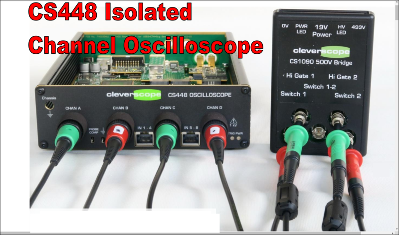
[Bart Schroder] was busy designing high voltage variable speed motor drives and was lamenting the inability of a standard scope to visualise the waveforms around the switch transistors. This is due to the three phase nature of such motors being driven with three current waveforms, out of phase with each other by 120 degrees, where current flows between each pair of winding taps, without being referenced to a common notion of ground. The average scope on your bench however, definitely is ground-referenced, so visualising such waveforms is a bit of a faff. Then there’s the fact that the motors run at many hundreds of volts, and the prospect of probing that with your precious bench instrument is a little nerve-wracking to say the least. The solution to the issue was obvious, build your own isolated high voltage oscilloscope, and here is the Cleverscope CS448 development journey for your viewing pleasure.
The scope itself is specification-wise nothing too flash, it’s the isolated channels that make it special. It does however have some niceties such as an extra eight 100 Mbps digital inputs and a handy 65 MHz signal generator. Also, don’t reach for your wallets just yet, as this is a specialised instrument with an even smaller potential user base than a normal scope, so these units are rather pricey. That all said, it’s not the existence of the scope that is the focus here, it’s the journey from problem to solution that interests us the most. There is much to learn from [Bart’s] journey, for example, where to place the frontend ADC? Isolated side or not? The noise floor of the signal chain dictated the former.
The real trouble with building a multichannel isolated instrument of this nature lies in the isolation from the frontend to the common backend. The frontend needs power, so this is fed-forward via a beautifully designed bifilar wound toroidal transformer, which is a whole story in itself. The data are sucked out of the ADC via a pair of 4.375 Gbps compressed serial lanes, according to JESD204B, using custom made fibre-optic link modules. [Bart] illustrates numerous problems along the way, just to illustrate that building something like this doesn’t always work the first way you try. Clever(scope) stuff indeed
Need a high current probe as well? we’ve got you covered, and since we’re on the subject of isolation, how’s about an isolated USB serial board to keep your laptop safe?


Would love to see a 4 channel design that I can actually buy.
Just bought one for work from Tektronix. All four channels are isolated. Great for working both sides of a flyback power supply.
TPS2014B 100mhz and the TPS2024B 200mhz
i was so disappointed when i learned the common cheap scopes don’t isolate the grounds on their inputs. this sounds awesome!
I was both disappointed and had to replace some circuit parts when I found out!
@
Greg A said: “i was so disappointed when i learned the common cheap scopes don’t isolate the grounds on their inputs.”
Unless the User Manual specifically states otherwise always assume your scope channel grounds are common at the instrument input connectors, regardless of how much the scope cost. Isolated grounds are not standard, to get them often means having to specify an option. The only reason you have separate ground connections at the individual probe ends is to maintain signal integrity, those grounds are normally tied together at the probe connectors. If you need a floating or differential input use two channels, invert one and add it the other. I have never seen a useful scope without built-in two channel invert-and-add capability as standard. Even if a scope has isolated ground capability (i.e. differential or isolated inputs) those channels will also be able to use common grounds (i.e. single-ended mode) and the invert-and-add capability will also be present.
This really makes me wonder how Tektronix solved the isolation problem in their THS720 handheld scopes back in the 1990s. I used one at a long time ago job to watch waveforms to a motor that had a low side switched armature and a field coil switched with an H bridge. It was really cool to watch the voltage to the H bridge just flip when the controller switched the motor direction, knowing that a normal scope would just go poof at that point.
https://w140.com/tekwiki/wiki/THS720
“When confronted by scope calibration failures that say “Cal error, DC balance” and there are persistent DC offsets that increase with the attenuator settings try replacing U45 and U46. They are HP CNR201A analog optoisolators, now made by Avago as the HCNR201-300E. They send a low pass filtered version of the input signal across the isolation barrier to give the DC levels that can not cross the high frequency transformer isolation barrier. ”
A combination of things.
1. Transformer for isolation for the AC high frequency stuff
2. Optoisolators for the DC offset (and presumably the lower frequencies.)
The TEK THS720 scopes show up on the used market periodically. They bring from $300US to $500US still. They are short on features compared to modern DSO’s but their portability and isolation make them very useful still.
I’ve been watching eBay for these recently. There are a couple things to watch for. One is that the LCDs like to go bad. The contrast gets so bad you can’t see an image. Apparently the polarizer sheet on the front somehow goes bad. Replacement LCDs usually cost about $150. Or you can pull the LCD out, take it apart, strip the polarizer sheet off, clean the glass, and apply a new polarizer sheet you can buy online for like $5. Probably doable for the type of person that reads Hackaday and uses oscilloscopes.
The other thing to watch for is that they come with the original scope probes. They were special probes with no exposed metal on the BNC connectors. Because the scope isn’t connected to a safety ground, they didn’t want any exposed metal that could be at some high voltage that your scope probe ground is connected to. I often see these scopes on eBay sold with other random probes with metal BNC connectors, which should operate fine and not shock you as long as you don’t connect your ground to a high voltage then touch the BNC connectors. I personally don’t want to trust myself to remember to not touch the connectors while in use so I want the original probes.
The scopes with good LCDs, original safety probes, and the battery, charger base, and wall wart are the ones that will hit the $500 or more price.
If you can still see through the polarizer (i.e., you can see the screen) but it isn’t acting like a polarizer, you could try just placing another polarizer in front of it. Not the ideal solution, but cleaning the adhesive from the LCD without damaging it would be quite challenging.
The TEK222 scopes also had two isolated channels. Despite the scopes being so old and so limited, I still use mine when I need to simultaneously look at two signals that need isolation – like the example PWM motor driver in the linked article.
Sadly they are so slow (10MHz) that they just can’t cut it with modern electronics.
I was considering a cleverscope to satisfy my isolation wishes, but I just can’t hack a USB scope. If it was integrated into a single instrument, I’d have bought one on the spot!
Yes, you can buy isolated scopes (Fluke, etc) but I *HATE* buttons where knobs should be used. The closest I’ve come to date is a MicSig STO1000 series… knobs, battery operated (it can float), but all the channels have a common ground. They do have a trigger out, so they could potentially be daisy-chained to a second and third unit……
Picosope has a range of isolated scopes!
Unfortunately the Picoscope offerings are USB scopes… transportability out the window – now you don’t just have to carry the scope, you also have to carry a laptop.
And benchtop use – I want LESS clutter on my bench, not more!
There is a limitation to how useful high-voltage isolated scope inputs are: most scope probes only specify about 150 V CAT I isolation between their ground and the user’s hands. And that is for the better ones with insulated BNC connectors.
But of course in many cases 150V is perfectly enough.
Wouldn’t the Fluke Scopemeters be sufficient for this?
Be careful, I read online that not all of the Fluke Scopemeters have the channels isolated from each other. Some do, you have to check the model. Any battery powered scope allows you to not be tied to a ground through the power cord, but the two channels also need to be isolated from each other if you want to do the trick I mentioned somewhere else in these comments, where I connected one probe of the TEK handheld scope to a motor on an H bridge while monitoring other ground referenced signals on the same board with the other channel.
Why not use two channels in diff mode and leave the ground unconnected? The less between the source of the signal and the oscilloscope, the better to me.
A number of reasons (far from exhaustive- just what I have dealt with in recent memory. Read the linked article for a better introduction):
you still need a ground ref for each input, and that is tough when you have a differential signal floating on hundreds of volts
resolution loss for the same reason
additional noise
input impedance (both lumped impedance and capacitance)
Grossly oversimplified example: Think of looking at a 5V differential signal floated at 800V, on a 1000V range (100V/div on many scopes). If the resolution of the input is 10 bits (easy number), the input is 1.0V/count, giving a range of 5 counts for the signal needed. An isolated input allows use of a 10V range, giving 10mV/count, much more useful. At the same time, there are advantages in capacitance and input impedance.
Although I truly admire the determination and expertise of the original publisher, I will probably resort to continue using my differential probes for anything prone to ground-loops.
A Fluke Scopemeter with the associated probes (600V CAT III rated) will do the trick. I use my old 199c for measurements on switch mode power supplies with excellent results. BR Peter
That’s what I was saying! Portable oscilloscopes like those don’t have a normal ground connection to use.
Hmm regarding the original task, is this not a classic hi tech sledgehammer to crack a nut? Or alternatively since this is Hackaday, could we not get something satisfactory using much more low tech hardware?
Firstly for the motor we are surely talking about relatively slow PWM signals of the order of 10 kHz – 1 Mhz. Anything higher and you will be driving the H-bridge as an analog amplifier. Simple way to measure Current through the H-Bridge Fets is to measure temperature which can be done easily enough with relevant temperature IC, then do some Maths
Measuring the high side gate drive voltage is the hardest part but surely not to complex, because it is a low Z measurement, since any useful FET will have a large input capacitance so gate drive will be of the order of a couple amps and 10’s of volts at < 1 MHz. For this task at a pinch you can use a fast opto isolator in analog mode attached across the drive as done in many Isolated PSU's. Attach outputs to a reasonably competent A2D converter and job done. More fancy arrangements might use a digital isolator such as Si8640 used as primitive ADC driven by High side Driver floating supply.
Is Measuring Vout1, Vout2 really an issue? Both are low Z and can be measured referencing to ground, for which the current sense resustors are pretty much irrelevant, but subtract their value if you wish!
The Current sense resistors are similarly low z so can be measured with reference to ground.
The Cleverscope isn’t a hobby project. It is a commercial product that grew out of a specific need.
For certification testing, outputs must be directly measured, not inferred using math, even if the math is trusted and the components are well understood.
At that price, it’s a tough sell vs the Tektronix TPS2024B which is a stand-alone scope with much higher bandwidth but only 8-bit resolution for 1/4 the price…
I’m also confused about why they would go for bifilar wound toroidal transformers. That greatly reduces leakage inductance but increases coupling capacitance; I would much rather have separated windings to minimize coupling capacitance (and capacitive loading on the reference point of the circuit) and just design the power supply to deal with the leakage inductance (which isn’t as painful at low power as it is at high power).
“I’m also confused about why they would go for bifilar wound toroidal transformers. That greatly reduces leakage inductance but increases coupling capacitance; I would much rather have separated windings to minimize coupling capacitance (and capacitive loading on the reference point of the circuit) and just design the power supply to deal with the leakage inductance (which isn’t as painful at low power as it is at high power).”
Well this is indeed a good question. Sometimes good knowledge in digital and mixed signal doesn’t go hand in hand with good knowledge in power electronics.
From the linked document:
> “If Zload is inductive -as most motors are -current increases or decreases slowly when a voltage is applied.”
Wait, what? What is a non-inductive motor?
Does anybody have a part number for these optic transceivers? I can’t find it anywhere.
https://corporate.murata.com/en-eu/more_murata/techmag/metamorphosis20/productsmarket/module Already Terminated
What’s the advantage of this over using a high voltage differential probe with the scope you already have?
“A second way is to use a differential probe – but even good ones have poor Common Mode Rejection Ratio (CMRR) at high frequencies.
As an example the Tektronix P5200A has a CMRR of 30 dB at 3.2 MHz.
Now 3.2 MHz is a rise time of tr =1/ f = 100ns. Lots of modern switches are faster than that.
If you had a 680V bus (typical for three phase = 2 x √2 x 240V), the probe will generate a spurious response equal to -30dB of 680V = 0.032 x 680 = 21.8V.
That obliterates pretty much anything interesting. Why measure the gate drive you say?
Well after blowing up quite a few IGBT modules, I can tell you that the gate drive has to be right.”