SDS-Remote

SDS-Remote Brings Power-User Features To Siglent Scope

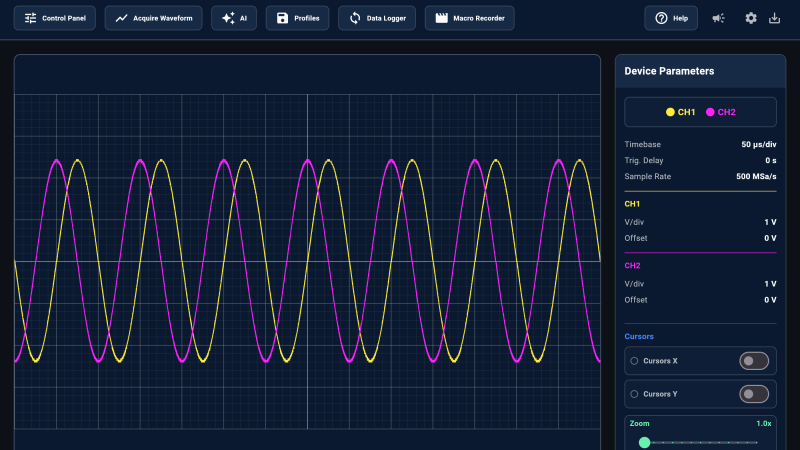
Many oscilloscopes have provisions to be connected to a computer and used remotely, but most of those interfaces are fairly rudimentary. To address this, [Winfried] has developed the SDS-Remote, a remote interface for the Siglent SDS 1000X-E series oscilloscopes.

The 1000X-E series oscilloscopes have both USB and network interfaces, and the SDS-Remote can use either (though the USB interface is still somewhat experimental). SDS-Remote allows for remote controlling the oscilloscope, capturing waveforms super handy as it lets you export a CSV file of the waveforms for further analysis. You can also capture screenshots of the scope through the web interface, making it much easier to compare waveforms as you’re working on a project. The built-in data logging lets you run long experiments and save out their results. The macro recorder lets you automate complex tests using SCPI commands and brings basic scripting to the interface without needing to run separate code. There’s also a mechanism to integrate an AI LLM to help translate common language into the correct scope configuration.

Thanks [Winfried] for sharing this awesome web interface for the oscilloscope no doubt it’ll be a welcome upgrade for those already remote controlling their Siglent scope. Head over to his GitHub page and check it out for yourself! Have you written any improved user interfaces for your equipment? Be sure to let us know what you’ve done so we can share with others who may find use in an interface that offers more than came with the product.

Continue reading “SDS-Remote Brings Power-User Features To Siglent Scope”

Two Bits, Four Bits, A Twelve-bit Oscilloscope

Until recently, hobby-grade digital oscilloscopes were mostly, at most, 8-bit sampling. However, newer devices offer 12-bit conversion. Does it matter? Depends. [Kiss Analog] shows where a 12-bit scope may outperform an 8-bit one.

It may seem obvious, of course. When you store data in 8-bit resolution and zoom in on it, you simply have less resolution. However, seeing the difference on real data is enlightening.

Continue reading “Two Bits, Four Bits, A Twelve-bit Oscilloscope”

Signal Processing Shenanigans: The Createc SC 01 Pocket Oscilloscope

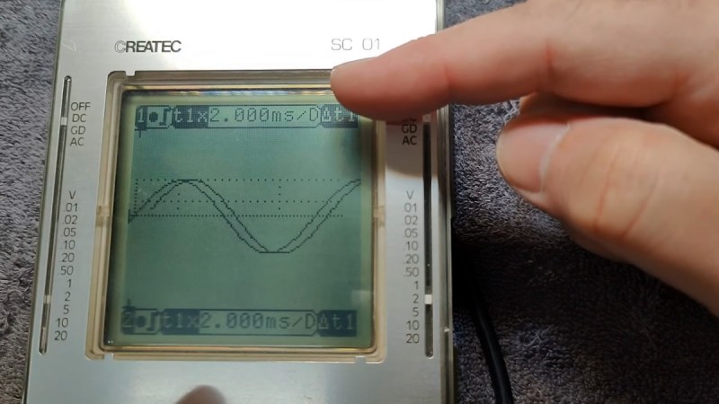
If you’re passionate about signal processing and retro tech, you’ll want to check out the Createc SC 01, a quirky handheld oscilloscope that recently caught the eye of [Thomas Scherrer] from OZ2CPU Teardown. This device, cheekily dubbed a “signal computer,” promises to be both intriguing and, perhaps, frustrating. You can view [Thomas]’ original teardown video here.

This device is packed with buttons and a surprisingly retro aesthetic that can make even the most seasoned hacker feel nostalgic. With a sample rate of 20 MHz and a bandwidth of up to 10 MHz, it’s a digital oscilloscope with a twist. Users may find its setup challenging, thanks to a somewhat convoluted manual that boasts numerous errors. However, beneath the confusion lies the potential for creative exploration: this signal computer can analyse analog signals, perform calculations, and even store data.

Despite its quirks, the SC 01 is sure the experience. Imagine troubleshooting a circuit while grappling with its unpredictable user interface—an adventure in itself for those who like a techy challenge.

The Createc SC 01 is not just another tool; it’s an invitation to embrace the imperfections of vintage tech. If you enjoy the hands-on learning process and don’t shy away from a few hiccups, this device might be something you’ll enjoy. Hackaday featured an article on similar devices last year.

Continue reading “Signal Processing Shenanigans: The Createc SC 01 Pocket Oscilloscope”

Supercon 2023: Aleksa Bjelogrlic Dives Into Circuits That Measure Circuits

Oscilloscopes are one of our favorite tools for electronics development. They make the hidden dances of electrons visually obvious to us, and give us a clear understanding of what’s actually going on in a circuit.

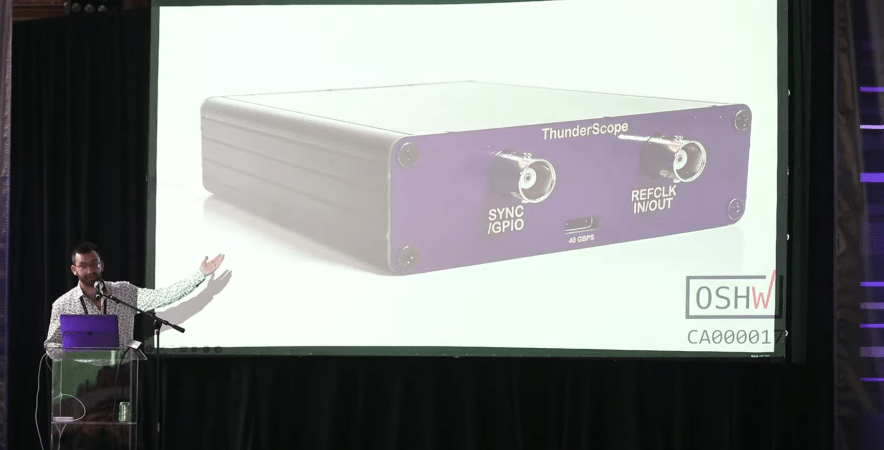
The question few of us ever ask is, how do they work? Most specifically—how do you design a circuit that’s intended to measure another circuit? Aleksa Bjelogrlic has pondered that very idea, and came down to explain it all to us at the 2023 Hackaday Supercon.

Continue reading “Supercon 2023: Aleksa Bjelogrlic Dives Into Circuits That Measure Circuits”

The Right Equipment Makes A Difference For Digital Oscilloscope Music

We all love our cheap digital oscilloscopes, and with good reason. But if there’s one place where analog scopes still shine, it’s anywhere you need X-Y mode. Digitally sampling the inputs and mapping them on the screen as discrete points just isn’t the same as steering an electron beam around a CRT, making X-Y mode work on digital scopes — at least the affordable ones — somewhat lacking.

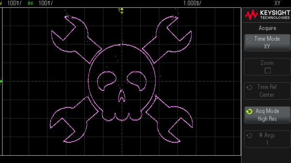
Thankfully, nobody told [Mark Hughes] that his digital scope would make a lousy X-Y display, so he just plunged ahead and figured out how to make it work anyway. The results are actually pretty good, but it took some doing. His setup begins with OsciStudio, an application built to take 3D shapes and animations and turn them into oscilloscope music. The output from that is piped to a USB sound card; [Mark] used a PreSonus Studio 26c, an adapter with DC-coupled inputs, which he found to be critical to getting good images. Also important was a USB isolator and good-quality cables, which greatly reduced jitter and made the image much more stable.

Displaying the image was as easy as connecting the left and right outputs from the sound card to the two scope inputs — [Mark] used a Keysight EDUX1052G — and setting it to X-Y mode. It took a fair amount of fiddling to get as far as he did, but we think the results speak for themselves. As for the sounds made by these images, he says it’s a bit like a hung sound card when a computer blue-screens. So, yeah — not exactly musical, but still an interesting way to have some fun with your digital scope.

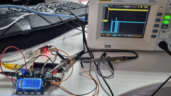
Showing the scope screen and the BeagleBone setup side by side, with GPIO input and output traces shown on the scope screen.

How Realtime Is Your Kernel? Scope A GPIO To Find Out

When debugging something as involved as kernel scheduler timings, you would typically use one of the software-based debugging mechanisms available. However, in cases when software is close to bare metal, you don’t always need to do that. Instead, you can output a signal to a GPIO, and then use a logic analyzer or a scope to measure signal change timing – which is what [Albert David] did when evaluating Linux kernel’s PREEMPT_RT realtime operation patches.

When you reach for a realtime kernel, latency is what you care about – realtime means that for everything you do, you need to get a response within a certain (hopefully very short) interval. [Albert] wrote a program that reads a changing GPIO input and immediately writes the new state back, and scoped both of the signals to figure out the latency of of the real-time patched kernel as it processes the writes. Overlaying all the incoming and outgoing signals on the same scope screen, you can quickly determine just how suitable a scheduler is when it comes to getting an acceptable response times, and [Albert] also provides a ready-to-go BeagleBone image you can use for your own experiments, or say, in an educational environment.

What could you use this for? A lot of hobbyists use realtime kernels on Linux when building CNC machine controllers and robots, where things like motor control put tight constraints on how quickly a decision in your software is translated into real-world consequences, and if this sounds up your valley, check out this Linux real-time task tutorial from [Andreas]. If things get way too intense for a multi-tasking system like Linux, you might want to use a RTOS to begin with, and we have a guide on that for you, too.

Isolated Oscilloscope Design Process Shows How It’s Done

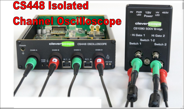
[Bart Schroder] was busy designing high voltage variable speed motor drives and was lamenting the inability of a standard scope to visualise the waveforms around the switch transistors. This is due to the three phase nature of such motors being driven with three current waveforms, out of phase with each other by 120 degrees, where current flows between each pair of winding taps, without being referenced to a common notion of ground. The average scope on your bench however, definitely is ground-referenced, so visualising such waveforms is a bit of a faff. Then there’s the fact that the motors run at many hundreds of volts, and the prospect of probing that with your precious bench instrument is a little nerve-wracking to say the least. The solution to the issue was obvious, build your own isolated high voltage oscilloscope, and here is the Cleverscope CS448 development journey for your viewing pleasure.

The scope itself is specification-wise nothing too flash, it’s the isolated channels that make it special. It does however have some niceties such as an extra eight 100 Mbps digital inputs and a handy 65 MHz signal generator. Also, don’t reach for your wallets just yet, as this is a specialised instrument with an even smaller potential user base than a normal scope, so these units are rather pricey. That all said, it’s not the existence of the scope that is the focus here, it’s the journey from problem to solution that interests us the most. There is much to learn from [Bart’s] journey, for example, where to place the frontend ADC? Isolated side or not? The noise floor of the signal chain dictated the former.

Continue reading “Isolated Oscilloscope Design Process Shows How It’s Done”