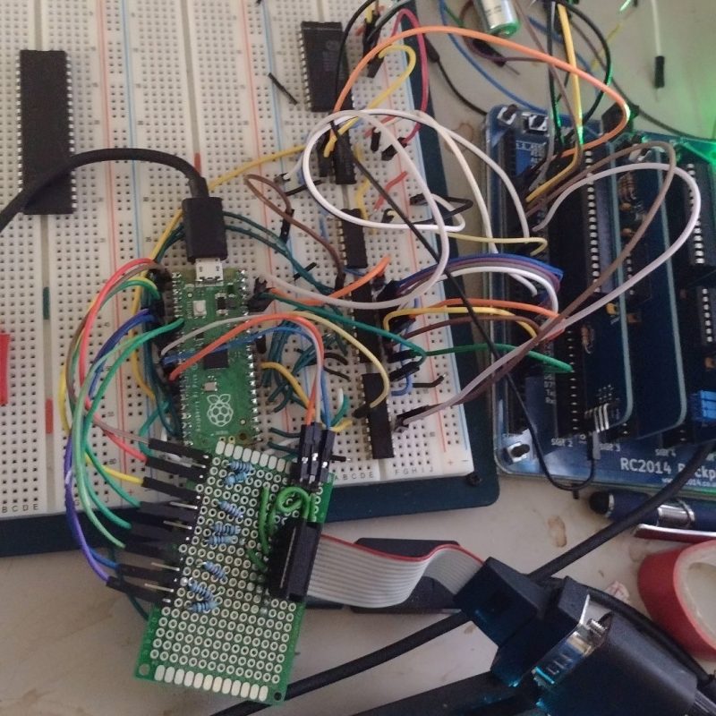
Building basic computers from the ground up is a popular pastime in the hacker community. [Kevin] is one such enthusiast, and decided to whip up a video interface for his retro Z80 machine.
74-series logic is pressed into service to handle address selection, enabling the Pico and Z80 to effectively communicate. Wait states in the Z80 are used to avoid the vintage chip tripping over when the two are communicating. The Pico outputs video in 160 x 120 resolution with eight bits of color per pixel, using a simple resistor-ladder DAC to do basic VGA.
The build serves as a great way to get familiar with programming both the Pi Pico and the Z80 itself. With that said, it’s probably possible to simply just emulate the Z80 on the Pi Pico given the latter runs at a default clock rate of 125 MHz, eclipsing the RC2014’s snail-like 7.3728 MHz main clock.
If you’ve been building your own retro graphics hardware, do let us know. We love that sort of thing around here!


First up! I love this RC2104 project. Something that grows out of strip (vero) board and becomes a kit is simplicity and easy understanding (education).
I think I have seen a number of Video outputs for this RC2014. One was probably just a CTTY terminal running on ??? an ATMEGA or something like that. Another was a processor on a more common module like an ESP8266 generating mono.
There was some talk about converting the open source GameDuino board to parallel access and using that. Seriously this would give high graphics capability (for something from the Z80 era) but I still think a Xilinx Spartan 3A is overkill. I think a Propeller was used as well in one video project. That is probably most suitable.
Now this. Unfortunately I’m not that impressed with using a modern high capacity MCU for graphics in this way. It doesn’t really fit the whole concept.
I would be more comfortable with a larger CPLD like the Xilinx XC9572XL/XC96144XL or Altera EPM570 which has enough resource constraints to make it a challenge.
The old “home computers” and indeed arcade games from the 6502 / Z80 era were all about how much graphics capability you could squeeze out of resource constrained chips and RAM. Much the same could be said of sound generation.
I’d look at it as a prototype for testing bus arbitration logic. Because in a video card, sharing the video memory between the video generation circuitry and the CPU is really the hardest part. Maximizing available access time and minimizing the wait states for the main CPU without graphics corruption (flashes).
Modern day SRAM or Synchronous SRAM are much faster than the memory cycles of Z80. You can do buffered writes/latched read data to stretch data hold time in a CPLD/FPGA and let the video have rest of the cycles. Video frame buffer is large block sequential, so a bit of FIFO + prefetch can be used for output.
Well, it’s not impossible. ;) But I find that you need increasing amounts of logic for increasingly efficient bus arbitration. Up to the point that the bus arbitration logic contains more chips than the whole video generation logic. At least, with processors that do not have fast enough ram access times to do interleaved accesses on the inverted dot-clock (CPU accesses are then ‘hidden’ from the video generator).
You go the other way around. A modern Z80 maxes out at about 20MHz clock by spec (Z84C020). Modern SRAM has 10ns from stable address bus and control to valid data or close to 100MHz cycle time. The Z80 requires a minimum of three clock cycles to execute the simplest instructions. The longer instructions take four clock cycles and there’s longer but they’re not used because they’re Longer. So. It’s very very simple to interface the SRAM to a Z80 or even multiple devices including a Z80 @ 20MHz when you are using multiple memory devices that have 10ns Access time.
The “bus” arbitration only needs to be timing efficient when the bus access requirements are close to the same frequency (clock domain). When then access requirements of one bus are twice the access time requirements of the other bus then the control logic is simple. At worst you have to buffer an address and the write data and another address and the read data. If the data written by the host process can’t be read back from (S)RAM until the completion of the write process then the host process cannot be aware of the delays.
Thank you for starting out with a little praise. A lot of these retro computing projects are about playing pretend and suspension of disbelief. VGA was introduced in 1987 IIRC, and the rc2014 is supposed to evoke the feelings of the late 70s. JB langston has an excellent tms9918a design, but it’s limited to composite out. People implement ansi terminals on hardware that could emulate the computers attached because it’s fun!.
The main reason I shared what amounts to a demo is that there are probably a few hundred people in the world that would like to implement functionality that would otherwise require ASICS/FPGAs, or CPLDs. The pico has the advantage of being cheap and DIP that can go into a breadboard. The method of WAIT allows doing things that don’t use DMA in micropython. It’s also possible to put together a through hole soldering kit for the rc2014 form factor (like the propeller board). I’m working on a tutorial series that goes over the code and the wiring – what took the longest was figuring out the syntax and operation of the rp2040 as there were no examples that I could find.
I was born in 1984, and I’ve always been fascinated with the early micros. Doing things this way is a middle ground between full emulation as Fabrizio Vittorio does with fabgl, and making a large board with binary counters, octal latches, etc. I grew up hearing about how the mos6502 and z80 powered the computers. The real heart and soul were the custom chips that generated sound and graphics.
An interesting but a strange endeavor like installing a V8 engine in a go-kart.
Or alien starship to house an obsoleted low tech space probe… Let there be whales? (pun intended)
Could emulate the whole thing instead.
Well if you haven’t put a Hemi 465 into a Morris Minor then you haven’t lived life yet.
I guess you could move the driver’s seat up to the roof.
B^)
You have to cut through the fire wall and remove both front seats to fit it in. Then you have to sit in the back seat to drive. Doing a couple of RHD to LHD conversions first helps. A large sledge hammer while the car is on it’s side helps make room for the drive shaft.
Funny, I heard the almost same analogy 15+ years ago when I helped someone installing Win XP on a PC that ran 98SE previously. :D
I’m not sure why he limited himself to such a low resolution. The Pico has enough RAM to handle 640 x 400 in 256 colours, or higher in lower colour depths. The PIO system is also more than capable of the required bandwidth (heck, you can get it to go direct to HDMI and skip the whole ladder DAC thing if you want).
The other thing that’s worth considering is a Text mode. The Z80 isn’t a speed demon by any means, but it’s quite capable of emitting text at a reasonable rate of knots. Make the PICO into a terminal for it (with graphics modes if needed).
In case of analogue TV-compatible signals,
640×400 (interleaved) would have been nice, yes. ^^
Or 640×200, at least (progressive).
VGA, of course, can do progressive scan all the time in these resolutions.
When I hear of the Z80, I can help but must think of the Sharp MZ series and the MSX computers.
The MZ-800 had colour text-mode, but also graphics modes – 320 x 200 8c / 640 x 200 mono.
The MSX series had 256×192 16c (MSX1), 256×212/424 256c to 512×212/424 (MSX2), 256×212/424 @12499c etc. etc.
The Turbo R’s also used a fast Z80 compatible, the R800.
https://www.msx.org/wiki/ASCII_DAR800-X0G
https://www.old-computers.com/museum/computer.asp?c=208
JB Langston has an excellent rc2014 form factor design for the TMS9918a. You can build your own MSX based on the rc2014 extended bus.
If you use a CPLD from ATMEL – the ATF1508, you can get it to do VGA quite easily. Cerberus 2080 has done that already and explains the CPLD very well… (Also covered on hackaday)
That really got my attention. A 5Volt CPLD that’s still in production. Then I though only 128 Macro’s is a bit tight so I went looking for the next biggest CPLD and no! that’s it, max 128 macro’s on a 5V device.
128 Macro’s will probably get you to a lower res statically positioned BMP like display which is usable with a Z80 but nothing is going to be fast. It might even get you to a 6845 CRTC like scroller but it’s not going to get you to hardware sprites.
There’s still the EPM570 I spose. I will have to see what can be done with that.
It will do 800×600 VGA monochrome no worries… That’s all I need for my TRS-80 Model 1 clone…
From memory the TRS-80 Model 1 had an output of 384×128 pixels but that was not addressable that way.
What was addressable is 64×16 or 32×16 ASCII like characters or 128×48 graphics blocks (pixels).
One character was 5×7 pixels and it was in a character cell of 6×8 pixels to provide spacing. There were 128 graphics characters that had 2 boxes across and three boxes down on one character cell that then provided the 128 horizontal pixels (64×2) by 48 vertical pixels (16×3).
All of this fitted onto 1K video RAM 1024 (64*16) bytes.
https://cdn.hackaday.io/images/4903791433073969001.PNG
More here : https://hackaday.io/project/5565/logs
For clarity; Is it ” a popular single-board 8-bit computer kit” or “a modular 8-bit computer” ?
Thank you for pointing that out. I changed the repository.
Do not like! I really hate seeing these retro computing projects that use things like micro controllers more powerful than the z80 itself or even full on Pis to perform video output. You’re using something more powerful than the computer itself just to output video. You could probably nearly emulate a z80 on a Pico and for sure emulate it on a Pi. If you’re going to go that route you might as well just emulate the whole PC. You can still pickup proper CRTC chips on ebay, or just do it the really budget way that things like the trs80 or zx spectrum did and drive the video with the z80 itself plus some logic gates. Design it to output composite like a retro computer would have done, and if you really must get an external composite to vga/hdmi adapter. I would consider that a much more faithful reconstruction of a retro computer.
Hi. I feel your pain. Personally, I’m torn back and forth when it comes to such creations. The last time I felt that way was when I saw that Pi-based RGB to HDMI converter for the Commodore Amigas. A full-blown Linux system (?) that tediously does the HDMI generation in software.. Ugh. On the other hand.. I’m glad that people do homebrew so enthusiastically these day, no matter with what technology. So I’m really glad that projects like this exist.. ^_^
I have no problem if you make your retro computer output a proper retro video signal then use whatever means you want between the computer and preferred display device to display it. It’s when you make the microcontroller that’s many times faster than the retro computer itself part of the computer. Hell I wouldn’t be against an FPGA being used as a drop in “CRTC”, even though they aren’t totally retro, at least you are recreating the logic that might have been spread across a pizza box sized board. It really wouldn’t be much different than a retro pc back in the day that used a custom ASIC to do it’s display output. an FPGA is the closest the hobby community can get to creating an ASIC.
I wonder if the Pi pico could be configured to be pin compatible with a TMS-9918a chip?
Given that the F18a 9918a is incredibly hard to get, this could be a decently cheap alternative.
Someone surprised me and mentioned a 5Volt CPLD with 128 Macros that is still in production (AFT1508) so I thought I might go and see if something like the TMS9918A would fit into it. Sadly no. There are larger ones in the series but they get expensive and are 144pin. It might fit into a 5Volt tolerant EPM570 though , maybe just, maybe not.
It’s quite a good chip for what it does and I can see what ended it’s production life. There is no RGB output, only composite and color is already modulated so it can’t be carried over to more modern formats like VGA screens.
I might dust off some old EPM570’s and have a play.