The default for any control project here in 2019 was to reach for a microcontroller. Such are their low cost and ubiquity that they can be used to replicate what might once have needed some extra circuitry, with the minimum of parts. But here we are at the end of 2021, and of course microcontrollers are hard to come by in a semiconductor shortage. [Hesam Moshiri] has a project that takes us back to a simpler time, a temperature controlled fan the way they used to be made, without a microcontroller in sight.
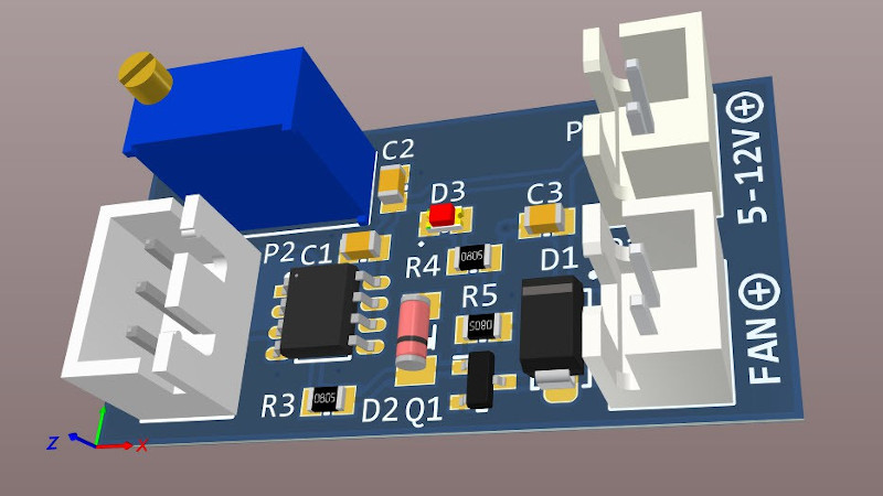
Old hands will no doubt guess where this design is heading, there is an LM35 temperature sensor producing a voltage proportional to its temperature, and half of an LM358 which forms a comparator against a static voltage from a divider. The LM358’s output drives a MOSFET which in turn switches on or off the fan motor. This type of circuit used to be the daily fare of simple control electronics in the days when a microcontroller represented a significant expense, and it’s still a handy circuit to be reminded of.
Have you forgotten sensors such as the LM35 in a world of on-board sensors? Time to refresh your sensing memory.


Nice simple analog stuff, but would have been better with a 555 (either with 4 pins PWM controlled fan or direct driving), as ON/OFF fans tend to be fairly irritating for humans around.
Probably depends on the application. The circuit is designed to adjust the fan speed by the input voltage, so you can make it more or less imperceptible by slowing down the fan slightly, or using a quieter fan.
Only thing I would add is some hysteresis to the switch, because the temperature sensor is drifting around slowly enough that it will reach a point where the output turns half-way on. The sensor is putting out 10 mV/C and the LM328 has an open loop gain of about 100,000 so there is a small window of about 1/100th of a degree where the op-amp output is not determined. The second problem is that 50/60 Hz mains noise around the set point can cause the circuit to buzz on and off. The third problem is that turning the fan on will cool the sensor by a small amount and shut the fan off almost instantly, flipping it on and off in a cycle of a few seconds.
You can add hysteresis by placing a small value resistor between P2-2 and U1A-3, then a large value resistor between U1A-1 and U1A-3. When the output goes high, it nudges the apparent temperature signal a bit higher, so when the actual temperature returns back to the set point it doesn’t immediately switch off. If the output swing at U1A-1 is about 10 Volts, then the ratio of the resistors should be 1:1000 for a hysteresis of 1 degrees C.
LM358B that is, not LM328
Besides hysteresis, there’s the possibility of wiring up the spare U1B op-amp into a relaxation oscillator to generate a voltage ramp. Then you modulate the temperature set point voltage using that voltage ramp, so the set point is continuously cycling between some value plus minus some degrees C. This happen simply by summing the oscillating voltage to U1A-2 through a large value resistor. It’s basically the same thing as the problem with the 50/60 Hz line noise making the fan buzz, except you’re doing it deliberately at a much higher frequency that you can’t hear.
This has the effect where the output will be off when the temperature is below the modulation range, PWM modulated within the range, and completely on above that. The fan will turn on smoothly.
I prefer exponential fan curves as they are quiet and insensitive to minor thermal fluctuations (e.g. burst loads) and can crank up quickly when you need real cooling.
(You only need an opamp, 1 diode and a resistor to make Exponential output).
Yyeah… kinda. But you’re implying linear mode operation and a fan requires up to 500 mA of current, so actually driving the fan is not so simple like that.
But here’s the thing: if you make an asymmetric RC relaxation oscillator that quickly resets to zero volts and then charges up towards V+, you’ll create a sawtooth wave which has the shape of an exponential (1- e^-t) according to the RC step response function. When you compare that waveform to some signal with the op-amp, you’ll automatically create an exponential PWM output. Then it’s just a matter of scaling and shifting the PWM reference signal to the level of the temperature sensor to set when the fan starts turning and when it gets to full power.
Of course with op-amps being poor comparators (they’re slow to switch fully on/off), the PWM frequency can’t go very high without distortion. Whether it works up 20 kHz and above is up to the component. An LM358B probably won’t, but it’s worth the try.
What I mean by fan curve is that the transfer function can be easily implemented in analog circuit (opamp). I really don’t care how it is implemented. i.e. PWM is just an end to a mean.
There are much better ways to implement a PWM than generating your own ramp and comparator… Your average switch mode supplies already have these building blocks. e.g. you can inject a voltage into the feedback loop or even using thermistor/resistor as the divider.
It’s very simple and easy to implement, and it can be done in many different ways as opposed to relying on some special switch mode supply IC that you may not have available.
Example (falstad link):
https://tinyurl.com/y6yeygbl
Looking at that circuit its not adjusting speed, its just turning it off and on, so a 555 PWM would be a better design.
The speed is selected by the choice of input voltage, since all the components can accommodate a suitable range of voltages. Not all designs will do that.
I agree with the hysteresis because oscillators never do and amplifiers always will.
I was more concerned with the thermal drift of a common LM358 given that the sensor is only 10mV/C but it turns out the the thermal drift for the LM358 is only 7uV/C so all good there.
The fan he is using is one that is designed to be quiet. I have used them and their impressive especially for making PC thermal management.
Second half of lm358 can be used as triangle signal for simple PWM setup – just add small amount of triangle signal to threshold signal for comparator.
Indeed. The 555 is the electronics analogue of bacon. A truly amazing chip.
This semiconductor shortage may be a good thing. People will need to actually design electronics again.
design with what? Keep in mind it’s the cheapest stuff that gets made last, because of the lowest profit…
This needs more parts then a micro would.
I swear I once saw a circuit that did something similar, except with 2 transistors instead of op-amp, and NTC instead of LM35.
It also had the advantage that the NTC could be replaced with a LDR as a automatic outdoor light controller, like so your Christmas lights ain’t on when it’s bright outside.
That might have been a “long tailed pair”, and it’s the basic building block inside an op-amp.
https://en.wikipedia.org/wiki/File:Long-tailed_pair.svg
That’s my standard go-to method. Four components: NTC and a resistor to set the bias point, a 5.6V Zener, and a Darlington. That’s all.
I have somewhere a tiny fan controller PCB from broken ATX PSU, that used single transistor to control the fan with NTC. I’ve also seen similar, simple one-transistor circuit that drove a heating element in DIY OCXO…
Ground connected to voltage divider adjustable resistor pot connected to thermistor to Vcc+. resistor-thermistor connection to base NPN transistor, NPN emitter to ground through 2.4 v zener, NPN collector to Vcc+ through 10k resistor>PNP transistor base to connection of NPN collector-10k resistor, PNP emitter to Vcc+, PNP collector to motor +, motor – to ground. Adjust pot for temperature turn on. Stick build it and embed it in hot glue and wrap it in heat shrink as a module with 3 wires sticking out of the stick. Clamp it on device you want to cool.
2k2 Ntc with lm317 and one 10k trimmer does the job here.
Sure, but your LM317 will then add about 1-2 Watts of waste heat to your device enclosure as the fan speed drops, and you have to keep cooling the regulator.
I made something similar for a fish tank thermometer, using a 741. Comparator with hysteresis, and one junction in a bottom-of the draw transistor for the temperature sensor. The 741 has a rare state it gets into where it latches up, and caused the fish to die. Happened twice while I was student, before I could afford a more expensive op-amp.
I mean a fish-tank thermostat to turn the water heater on and off (not thermometer).
The author suggests mounting the sensor to the heatsink using silicone glue. Silicone glue is something of an insulator, and will cause increased hysterisis in the system. A metal-filled epoxy such as JB Weld would be a better choice (or just bolt/clip the sensor to the heatsink w/o adhesives).
I guess they mean silicone thermal paste, such as is used for heatsinks, exactly for it’s good thermal conductivity.
https://www.amazon.com/silicone-heatsink-compound/s?k=silicone+heatsink+compound
The metal/metal oxide/ceramic/carbon particles are the active ingredient of the thermal paste. The silicone (liquid form) acts like a binder. It is still better conductor than an air gap.
I did the same 30 (?) years ago to run a solar water heater. A string of 1N4148 diodes gives the same output as an LM35 and is cheaper. I made a differential thermostat with hysteresis out of an LM339 comparator, and run a solid state relay to switch a 1/20 HP pump. Some loads stall out if you try to vary the power into them.
There is even a simpler way. Dallas semi has a 3 pin temp sensor that is programable. So when you hit your temp mark, one of these pins changes state. So i could be reduced down to the temp sensor and a fet.
There is even a simpler way. Just use a thermostatic switch. You can get them in N.O./N.C. varieties and switching at different temperatures.
Some of the fancier ones (those with a bulb at the end of a long, thin tube) are even adjustable, though they tend to be in the range suitable for a household boiler, or fridge/freezer.
The mos will work in its linear curve, dissipating power depending on the current of the fan. So for small fan maybe this is ok but for larger fan , much better a pwm driver circuit….which can be easily achieved with? A micro.