A few months ago, I was discussing the control of GPIB equipment with a colleague. Based on only on my gut feeling and the briefest of research, I told him that the pricey and proprietary GPIB controller solutions could easily be replaced by open-source tools and Linux. In the many weeks that followed, I almost abandoned my stance several times out of frustration. With some perseverance, breaking the problems into bite-sized chunks, and lots of online searching to learn from other people’s experiences, my plan eventually succeeded. I haven’t abandoned my original stance entirely, I’ve taken a few steps back and added some qualifiers.
What is GPIB?
Back in the 1960s, if test equipment was interconnected at all, there weren’t any agreed-upon methods for doing so. By the late 60s, the situation was made somewhat better by card-cage controller systems. These held a number of interface cards, one per instrument, presenting a common interface on the backplane. Although this approach was workable, the HP engineers realized they could significantly improve the concept to include these “bridging circuit boards” within the instruments and replacing the card cage backplane with passive cables. Thus began the development of what became the Hewlett-Packard Interface Bus (HP-IB). The October 1972 issue of the HP Journal introduced HP-IB with two main articles: A Practical Interface System for Electronic Instruments and A Common Digital Interface for Programmable Instruments: The Evolution of a System.
To overcome many of the problems experienced in interconnecting instruments and digital devices, a new interface system has been defined. This system gives new ease and flexibility in system interconnections. Interconnecting instruments for use on the lab bench, as well as in large systems, now becomes practical from the economic point of view.
HP subsequently contributed HP-IB to the IEC, where it became an international standard. Within a few years it become what we know today as the GPIB (General Purpose Interface Bus) or IEEE-488, first formalized in 1975.
The Task At Hand
Why did I need to use a 50-year old communications interface? Since GPIB was the de-facto interface for so many years, a lot of used test equipment can be found on the second-hand market for very reasonable prices, much cheaper than their modern counterparts. Also, the more pieces of test equipment ending up on lab benches means less of them end up in the recycling system or landfills. But I don’t need these justifications — the enjoyment and nostalgic feeling of this old gear is reason enough for me.
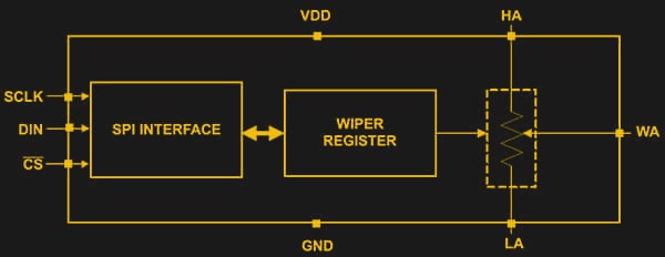
But why would you want to talk to your test equipment over a computer interface in the first place? In my case, I had a project where I needed to calibrate the resistance of a digipot at each of its programmable wiper positions. This would let me create a calibration algorithm based on measured data, where you could input the desired ohmic value and obtain the corresponding wiper register value. Sure, I could make these measurements by hand, but with 256 wiper positions, that would get tedious real fast. If you want to learn more about digipots, check out this article from the Digikey’s library on the fundamentals of digital potentiometers and how to use them.
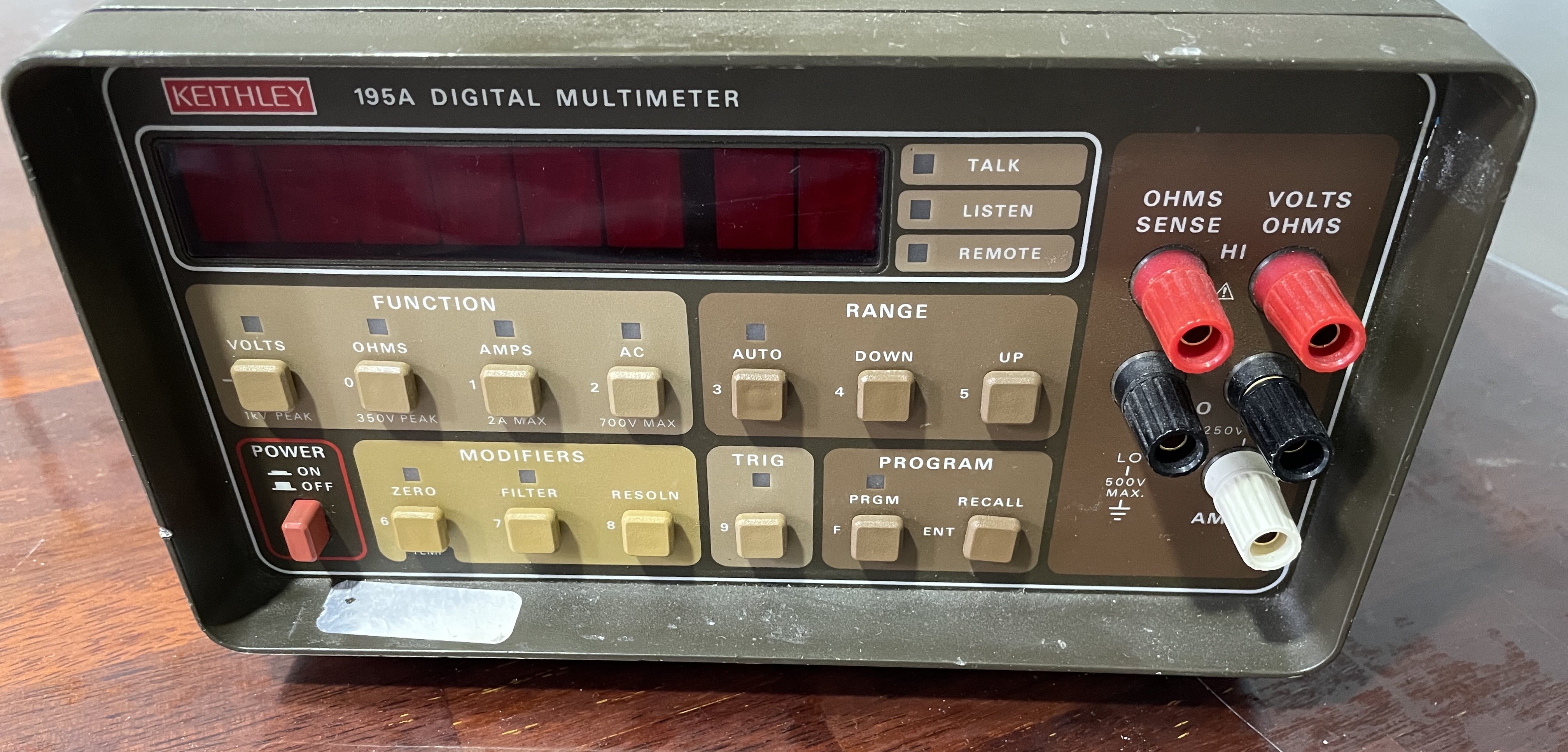
I scored a used Keithley 195A digital multimeter from the early 1980s. This is a 5-1/2 digit bench DMM, and my unit has the Model 1950 AC/Amps option installed.
Plan of Action
While searching around, I found a thesis paper (German) by [Thomas Klima] on using an easy-to-build GPIB interface shield on a Raspberry Pi or a Pi Zero to communicate with lab instruments. His project is open source and well documented on GitHub pages (Raspberry Pi version here and Pi Zero version here) his elektronomikon website.
It is a simple circuit, supporting my gut-feeling assertion that GPIB is not that complicated and you could probably bit-bang it with an 8051. I assembled the project, and I had a Raspberry Pi Zero-W all ready to go.


Software wise, the shield utilizes the existing Linux kernel module linux-gpib. It looked easy to install and get running on the Pi in short order. After a couple of hours installing PyVisa and some instrument-specific libraries, I should be automatically recording data with Python scripts in less than a day. Alas, reality doesn’t always match our expectations.
GPIB Architecture
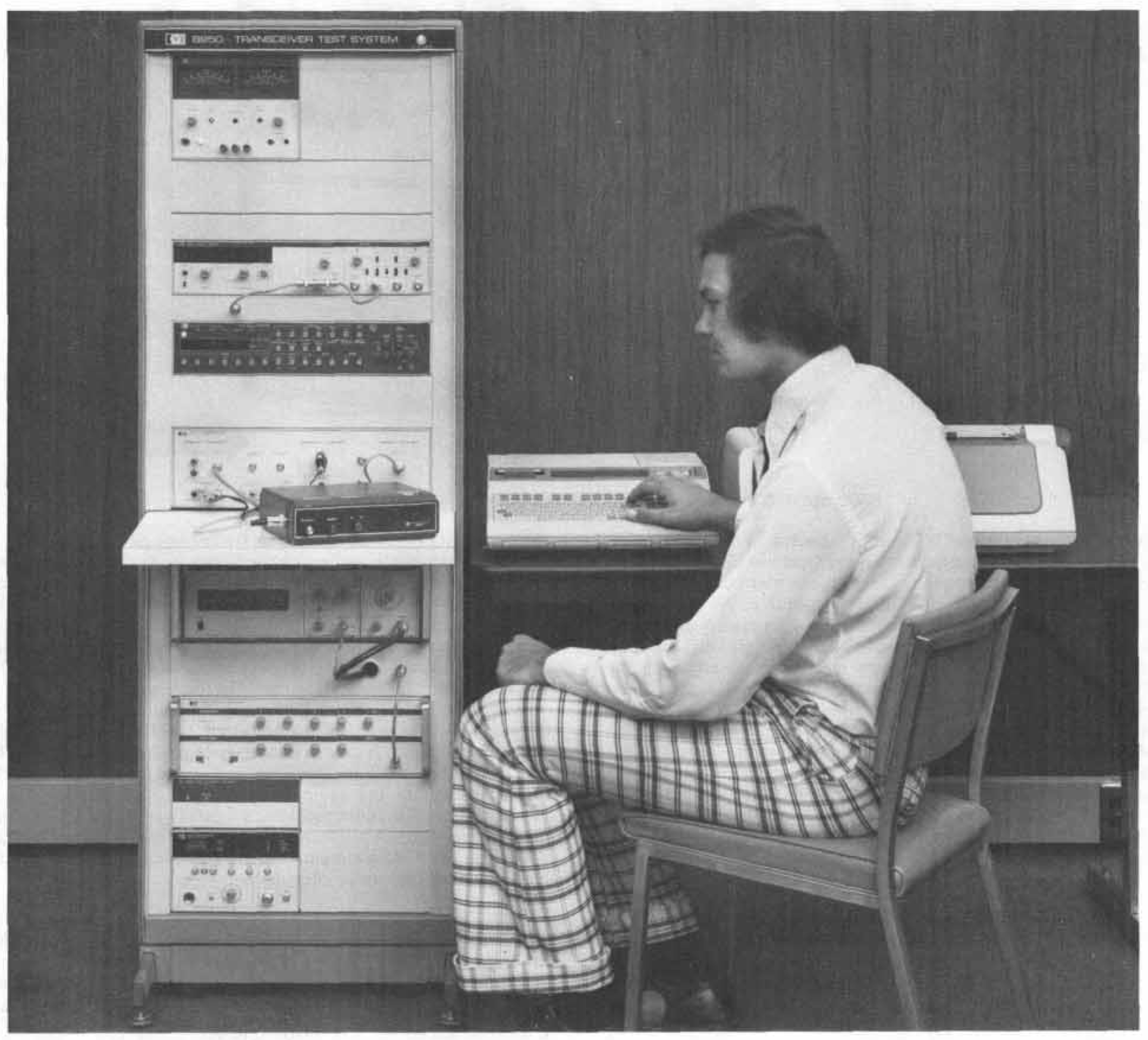
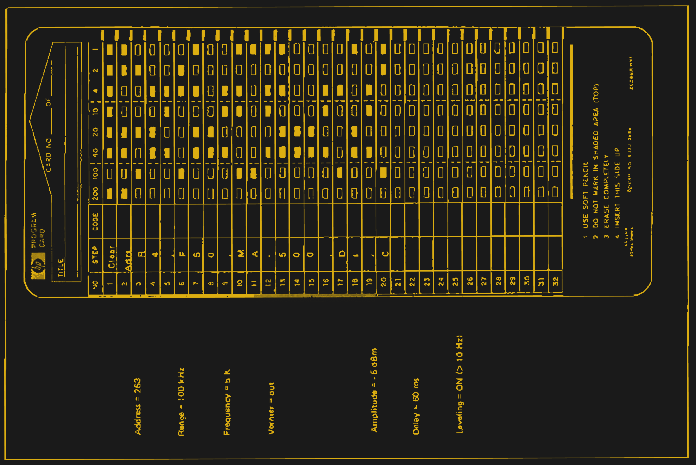
A little background perspective will be helpful in understanding the concept of GPIB. If we visited an electronics lab in the 60s, using a computer to control repetitive test sequences was the exception rather than the rule. Instead, you might see magnetic tape, paper tape, magnetic cards, or even cards onto which commands were marked in pencil. And for some setups computer control might not even be needed. For example, a temperature sensor might directly plot on a strip chart recorder or save values on a magnetic tape drive. If you remember that this is the world in which the HP engineers were immersed, the architecture makes sense.
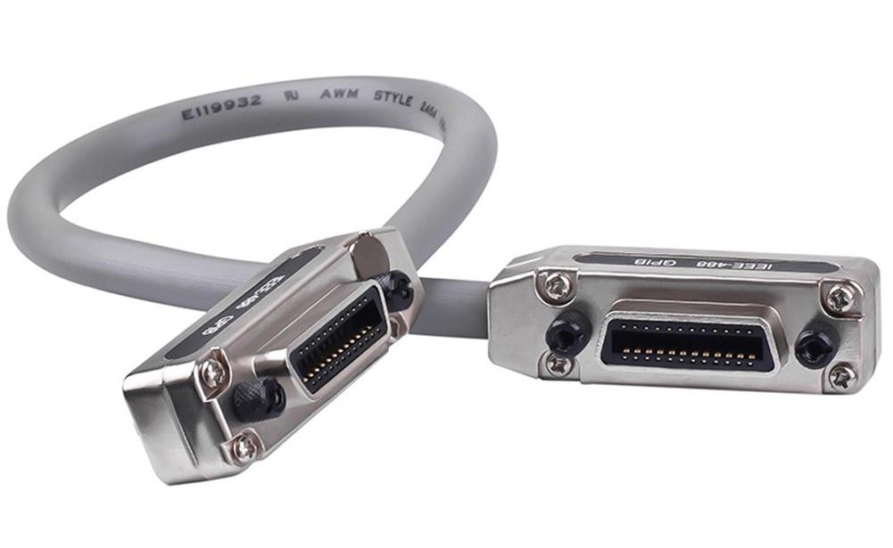
The GPIB is a flexible interconnection bus using 15 signals: 8 bit data bus and 7 bits of control lines. Any device on the bus can be a passive listener or an active talker. A talker can speak to multiple devices at the same time, and devices can raise an interrupt if they have an event that needs to be serviced. Devices are interconnected using cabling and connectors which were small for their day, but are a nuisance compared to today’s USB, Ethernet, and serial cabling. The 24-pin Centronics connector allows for easy daisy chaining of devices, but is a hefty beast — in a pinch, you could use a GPIB cable effectively as nunchucks.
The traditional use of GPIB was a central control computer connected a chain or star cluster of test gear. This has historically influenced the available GPIB interface hardware. For decades, ISA and later PCI interface cards were installed in computers, or the GPIB interface might be integrated if you were using an HP computer. They tended to be a bit expensive, but since one interface board controlled all the instruments, you only needed one card in a given test setup. National Instruments has became the leader in the GPIB world of both interface cards and supporting drivers and software, but their proprietary software and reputation for steep prices is a bit off-putting for many small companies and home labs.
You can certainly implement an automatic test setup entirely using GPIB cabling, 1970s-style. Many such legacy systems still exist, in fact, and still have to maintained. But more than likely, our use of GPIB these days would be to adapt one or two instruments so they can be used in your non-GPIB test setup, be that LAN, USB, serial, or some combination thereof. This turns the economics of the situation upside down, and is why low-cost GPIB adaptors for just one instrument are sought after.


Let the Problems Begin
The Pi Zero-W has built-in WiFi — in fact, that’s the only LAN connection unless you connect up external circuitry. But I couldn’t get it to connect to my WiFi router. For the longest time, I thought this was an operator error. I have quite a few Raspberry Pi 3s and 4s using WiFi mode with no issues. As I started troubleshooting the problem, I learned that the network management tools in Debian / Raspberry Pi OS have changed over the years. There are many tutorials showing different ways configure things, some of them being obsolete.
A headless Pi Zero-W was really dead without any LAN connection, so I assembled a rat’s nest of USB cabling and an HDMI adaptor so I could at least get a prompt, and ordered a couple of USB-LAN adaptors to get me online temporarily. Hours and hours of searching and testing ideas, I finally found a couple of obscure posts which suggested that the Pi Zero-W’s radio had problems connecting in some countries — South Korea was on that list.
Indeed this was the issue. I could temporarily change my router’s WiFi country to the USA, and the Pi Zero-W would connect just fine. I couldn’t leave it like that, so I switched back to South Korea and continued using wired LAN cabling for my immediate work. This particular problem does have a good ending, however. On the Raspberry Pi forums, one of their engineers was able to confirm the bug, and submitted a change request to Cypress Semiconductors. Some weeks later, we got a proposed updated firmware to test. It solved the problem and hopefully will be added in an upcoming release.
Router Goes Crazy
At this point, I have a couple of Pi Zeroes, a Pi 4B, and a few USB-LAN adaptors all working. Since these USB-LAN adaptors can move around — an adaptor could be on computer ABC today and on computer XYZ tomorrow — I carefully labeled each adaptor and entered its particulars into the /etc/hosts and /etc/ethers files on my router. And my network promptly died. This was tough to solve, because surprise, extracting information from the router is awkward when the network is frozen. I finally figured out that I had mistakenly crossed up two entries for the USB-LAN adaptors in the router’s tables, and this drove OpenWRT crazy.

This took so long to find and solve, my solution was a bit overboard in hindsight. First of all, I completely wiped the router and re-installed the firmware from scratch. I also took the time to better organize my hostname and static lease data. I found this Gist from [Krzysztof Burghardt] that converts your /etc/hosts and /etc/ethers into OpenWRT’s /etc/config/dhcp file, and tweaked it to suit my needs. I bought a second backup router that I can quickly swap over if this happens again. And last, but not least, I broke down and bought a label printer to clearly mark these USB-LAN adaptors with their MAC addresses.
Ready to Go
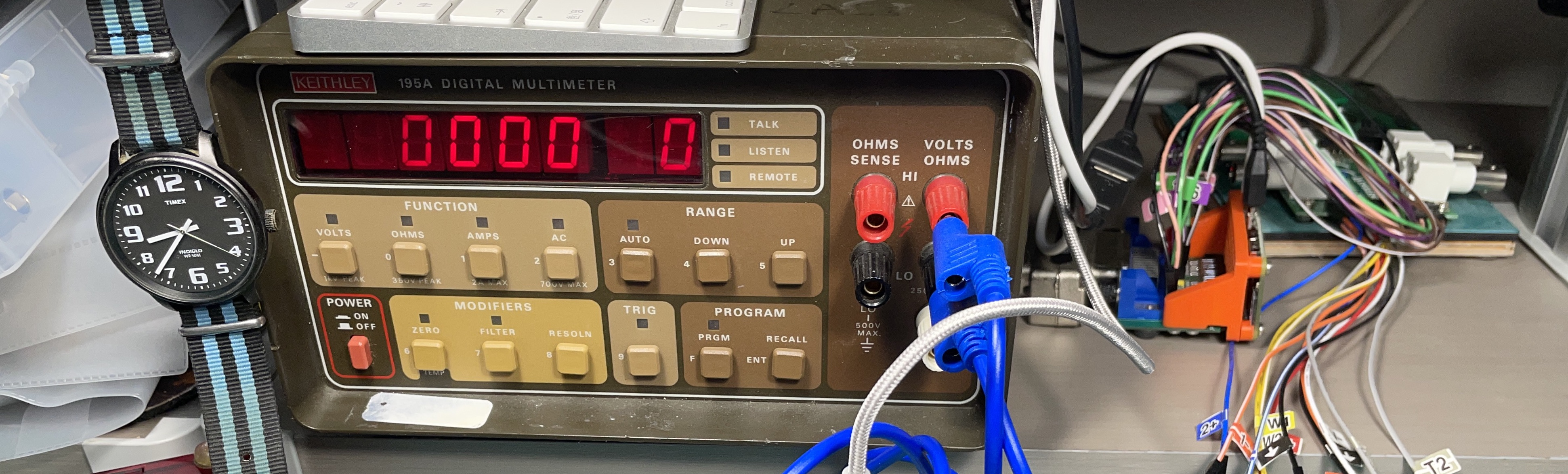
Finally, I’m ready to do real work on my project. Ignore the flying leads in the background are just for fun – they go to an Analog Discovery 2 logic analyzer to observe the GPIB signals. The wristwatch is a nod to my laziness — I put an old smartphone on a tripod to watch the meter in the lab, and monitored it from my office desktop PC while testing Python scripts. Every once in awhile the video would lock up, and I used the second hand as a sign of whether things were running smoothly or not. In part two of this saga, I’ll wrap up the measurement story, give some more information on GPIB and its revisions, and show graphs from my automated test setup.


I did this at one of my jobs.
Replacing gpib interfaces with usb. Its not that big of a deal as long as its well documented
Yep, same here. I bought a GPIB to USB adapter, sent it command via the serial port, and had no trouble at all getting it to work. The adapter was around $15, I think. I was controlling an RF generator and a spectrum analyzer.
Hi Tim, can you please give me the url of this cheap GPIB to USB Adapter? Thank you
Regards Boris
Get a Commodore PET. I’ve read that companies bought them because of the GPIB interface, thiugh I don’t recall how well it worked.
Ahh yes, we had a PET in the electronics lab at Uni in the ’80’s and GPIB was what it was used for mainly.
As I recall there were various PEEK and POKE statements to get at it? But that part is hazy.
I can’t remember what equipment was connected, probably just a V and A meter. Maybe temperature too.
A truly horrible decision. It was a nightmare to use directly from software and incredibly slow. I did one project porting something to the C64 in the 1980’s and never touched one again.
The Commodore 3000 series for sure used GPIB to communicate with its printers and floppy drives. It obviously worked rather well. The only real problem was the weight of these stacked connectors as they could snap the computer’s PCB.
The later VIC-20, C64 and even C128 used a cannibalized version with only a single data line.
When I was in high school back in the early ’80s, there was a room with 8 or so CBMs, all hooked up to a single floppy drive by stacking GPIB connectors on the back of the floppy drive. (presumably so they could load the same courseware off of one floppy without needing to pass it around the room)
It was rather surprising to see, wierd stuff even to a Byte subscriber like I was then.
GPIB (the physical layer) is a bit of a nightmare, but many even remotely modern devices have a USB or RS232 connection which uses the same SCPI (the application layer) command set.
VISA’s happy swapping between the two just by changing the resource name. GPIB, serial, or TCP/IP access.
Super-nice thing would be to just use something like an ESP8266/ESP32/etc. and then just listen on a TCP/IP port and pass the received SCPI commands to GPIB and back. Poof, cheapo GPIB-to-wireless.
There are ESP32-to-GPIB projects out there, but I don’t think any of them act as SCPI passthroughs, although maybe I’m missing something.
If you want to use GPIB, use an Arduino running AR488 with ribbon cable and IDC connectors. It’s $15 for the Arduino and $5 for each device on the bus up to a limit of 10. If you want wireless add a Pi.
If you’ve got GPIB capable gear you want to use GPIB as this lets you run the same series of tests automatically using multiple instruments.
Check EEVblog for details on AR488
It’s this project: https://github.com/Twilight-Logic/AR488
Thanks for that. I’ve got various software written for a “clone of a clone” of Prologix e.g. https://github.com/MarkMLl/hp2671 and will knock one of those together when I have time.
Chris, you can easily get an ethernet interface from the Pi’s USB through USB OTG. With a tiny bit of config on the SD card you get networking very quickly. Maybe that you don’t even need config when using DHCP.
And instead of watches, you can use maneki nekos for the checks like CCC does.
If you want a fairly robust solution for more $, Prologix makes a usb to gpib converter that plugs into a rpi and runs fine via serial to /dev/ttyUSBx, or for even more $, NI as noted makes converters. NI also makes something even weirder, a GPIB-to-USB converter so a dedicated GPIB system can communicate with a modern scope that only provides a USB SCPI interface. (GPIB and USB are so wildly different that you can’t just use a usb2gpib in reverse.) And if you’re really wanting high performance, you can get rpi’s that have PCIE and stick a NI PCIE GPIB card in there. There are open source programs out there for kernel-level GPIB support for fancy hardware like that, but they’re not trivial to get working.
The nice thing about GPIB is once it’s set up it’s really reliable. Setting up SCPI over ethernet or usb can be quite frustrating if addresses/enumerations change on reboot, and for some programs, it’s hard to get the controller to see fixed IP addresses on instruments. I’ve had some luck with setting up a DNS server on the control computer so it can assign repeatable IP addresses to the instruments, with them all set up with DHCP, but that too is frustrating.
In contrast, with GPIB you make sure each instrument is set up to a different number, plug it all in, and it’ll work for decades.
Side note: if you find really old HP equipment, stuff prior to about 1980, they used imperial threads on the GPIB connectors, while all the gigantic hordes of stuff made since then have metric threads, so you want to be careful about that.
Prologix also has a GPIB to Ethernet adapter, which is very easy to use.
Yep, we use a dozen of them, at work, to control old big power supplies, Keithley multimeters, and so. They work very well.
But I would be very interested in a GPIB lib for RPi Pico, using its GPIOs…
This is an interesting task to be ported to the ESP32 as the RPi is a bit overkill and more pricey and Arduino doesn’t have WiFi. The firmware on a small ESP32 board, one for each instrument, could interface to the bus (Arduino libraries can be ported) then link to a central access point, encapsulate both ways the traffic so that a header identifying the source and destination is added. This way we first remove the 31 device limit, plus we can also have multiple PCs, even multiple programs on the same system, talking with multiple instruments. Imagine having 5 millivoltmeters measuring various test points on a circuit and a dashboard (that would be a good use for the RPi, or an old cellphone) in which all values are conveniently shown on the same screen, sent to a logger, printer, etc.
It sounds like the actual Pi to GPIB part was fairly easy, and you had trouble with issues more specific to you and your setup.
That’s what I thiught, but I skipped parts so thiught maybe I’d missed something.
Hence my Commodore comment. If it could be done with an 8bit computer with maybe 8K of RAM 45 years ago, surely a full blown system today shoukd have no problems.
The mechanics of it are easy and the specification is public. The question is whether you have the will, skill, and time to implement the ieee-488 standard on your desired platform. The only thing I would be hesitant about when moving from ieee-488 to something like ethernet is the timing. ieee-488 is very structured in its timing and its talk/listen modes. Ethernet by design is a much more free-for-all design with either collisions in half duplex or any time two way communications in full duplex. A lot of GPIB equipment will not like the idea of sending and receiving in this manner. You would have to buffer or prevent this kind of chaos from being seen by the end systems. USB is easier but takes away from the distributed bus architecture that GPIB was designed for. If I was doing it today, I would keep the GPIB interface on the test equipment side (after all it is already bought and paid for), all you need is an adapter from ethernet or USB to GPIB. They are not that expensive (we are just spoiled by super cheap components today).
>Ethernet by design is a much more free-for-all design with either collisions in half duplex or any time two way communications in full duplex.
Pretty sure that collisions are gone after full duplex and Ethernet switches (vs Old hubs, 10Base2 that share media among multiple ports).
There is really nothing inherently difficult about ieee-488 communications. The hardware is simply more expensive because it is not that popular, it just does not have the mass market to drive the prices down. It is also a parallel communications method which is complex in the current world which is highly serial. There is just not much market for parallel to serial convertors anymore. Remember this bus was used on test equipment that was very expensive back in its day so no one balked at the price. Now that IP over ethernet is so standardized, that would be the go-to solution today (not wireless, not in an electronics testing lab).
If you want to have a heart attack just go ahead and look for brand new name brand differential oscilloscope probes. The pricing on test equipment has everything to do with market size and nothing to do with bills of materials. You can easily spend many thousands on probes with five dollars worth of components.
MAN I’ve been trying to set up an arduino-based GPIB to USB converter with a 32u4 and some TI transiever ICs. It’s a holy pain, especially because I don’t have a big enough logic analyzer, nor are the datasheets clear, nor do I have anything other than my oscilloscope to test against.
Sounds like a worthy effort though. Would we be able to have a peek into your project on github or somewhere related? Thanks.
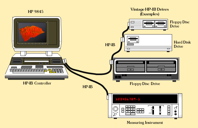
I worked for HP for ten years in Canada. I had a 9830 with HPIB interface and a rack of test equipment connected to it. I used that rack of equipment to run calibration tests on all kinds of instruments that had been sent in for repair. I primarily used it for RF test equipment such as spectrum analyzers, RF sweep generators and a mirade of other RF test gear. I wrote all the test software myself. I also wrote a calibration history program for the 9830 to track the calibration status of the equipment in our test and repair center. I loved HPIB. It was great. Ah!! the old days….I currently have a bunch of HPIB test gear in my own home lab that I have accumulated over the last 30 years. HP gear was always quality gear.
Oh, one other thing. Everything was written in BASIC….no python etc back then.
Hold it. It was a 9845 not 9830….Old timers…
Many years ago, in the days of analog Frequency Division Multiplex Analog microwave systems, I needed a way to evaluate the baseband for “hot” channels and noise levels across the baseband. I had a selective level meter with an HP-IB interface, and a matching HP signal generator with an HP-IB interface. We had an IBM PC-AT with Lotus 1-2-3 and a peculiar little plug-in called Lotus Measure. Using macros, I was able to control the signal generator, insert a signal in between channels on the sacrificial link in the network loop. Using that signal generator as a reference, we were able to measure baseband flatness.
Then I took our database of channel information and directed the selective level meter to measure the channel signal level. Any of the channels that were too far above the noise floor were identified and then we built up work orders to check the settings of those channel cards the next time we visited the site on the network.
My bosses saw the blinking lights, a spreadsheet populating itself, and the graphs of performance and, well, that’s how I got a promotion. I have many fond memories of controlling things with HP-IB. But that was in the late 1980s. We have better methods now.
Or do we?
>We have better methods now.
not everything that is old is outdated. GPIB is still around, and so is SCPI via ethernet (standardized TCP port 5025). As mentioned in https://hackaday.com/2021/11/17/scpi-on-teaching-your-devices-the-lingua-franca-of-laboratories/ we now also have an open source scpi-parser library, which shifts the focus in an interesting way: today we’re the ones using AND implementing equipment.
controlling and visualizing readings in a lab automation effort sure became easier with python and Jupyter Notebook, but the good stuff is here to stay.
Which selective level meter were you useing? I used to repair many of them back in the day.
Do it properly and get a HP 85 and then program in Rocky Mountain BASIC! Easy
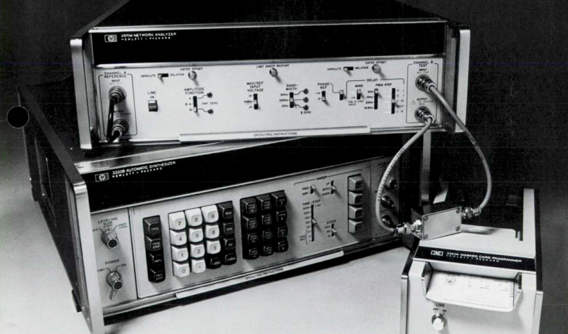
Hello, i’m very impressed, i use HP87XM with Dual Floppy Drive, HP3330A and the 3570A and is working nice for automatic network analyzing. But the 3570A has a problem, one Chrystal Filter 99.9985KC is defect and the Amplifier (100Hz & 10Hz -filter doesn’t) work. I’m looking for this spare parts. I have also some HPIB measurement equipment like spectrum analyzers.
Raspberry Pi is a very good idea and very interesting to use older HPIB- Equipments. Many thanks.