The powerbank PCB, with all the components on one side, 18650 holder on the other, a MicroUSB cable plugged into the PCB's MicroUSB socket

Open Hardware 5V UPS Improves On Cheap Powerbank Design

Often, we need to power a 5V-craving project of ours on the go. So did [Burgduino], and, unhappy with solutions available, designed their own 5V UPS! It takes a cheap powerbank design and augments it with a few parts vital for its UPS purposes.

You might be tempted to reach for a powerbank when facing such a problem, but most of them have a fatal flaw, and you can’t easily tell a flawed one apart from a functioning one before you buy it. This flaw is lack of load sharing – ability to continue powering the output when a charger is inserted. Most store-bought powerbanks just shut the output off, which precludes a project running 24/7 without powering it down, and can cause adverse consequences when something like a Raspberry Pi is involved.

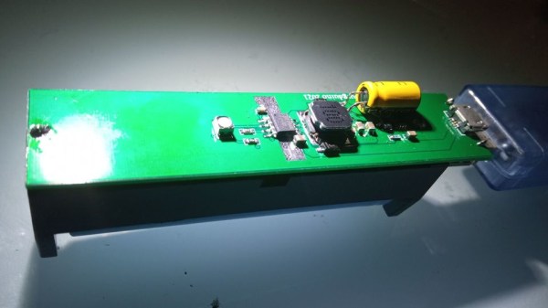
Understandably, [Burgduino] wasn’t okay with that. Their UPS is based on the TP5400, a combined LiIon charging and boost chip, used a lot in simple powerbanks, but not capable of load sharing. For that, an extra LM66100 chip – an “ideal diode” controller is used. You might scoff at it being a Texas Instruments part, but it does seem to be widely available and only a tad more expensive than the TP5400 itself! The design is open hardware, with PCB files available on EasyEDA and the BOM clearly laid out for easy LCSC ordering.

We the hackers might struggle to keep our portable Pi projects powered, employing supercapacitors and modifying badly designed Chinese boards. However, once we find a proper toolkit for our purposes, battery-powered projects tend to open new frontiers – you might even go beyond your Pi and upgrade your router with an UPS addon! Of course, it’s not always smooth sailing, and sometimes seemingly portability-friendly devices can surprise you with their design quirks.

A graph visualising approximation errors - the specific principle pictured is described well by the linked article

Time And Accuracy In Las ATMegas

Do you ever have to ensure that an exact amount of time passes between two tasks in your microcontroller code? Do you know what’s the difference between precision and accuracy? Today, [Jim Mack] tells us about pushing timers and interrupts to their limits when it comes to managing time, while keeping it applicable to an ever-popular ATMega328P target! Every now and then, someone decides to push the frontiers of what’s possible on a given platform, and today’s rules is coding within constraints of an Arduino environment. However, you should check [Jim]’s post out even if you use Arduino as a swearword – purely for all of the theoretical insights laid out, accompanied by hardware-accurate examples!

This will be useful to any hacker looking to implement, say, motor encoder readings, signal frequency calculations, or build a gadget processing or modifying audio in real time. To give you a sample of this article, [Jim] starts by introducing us to distinctions between precision and accuracy, and then presents us with a seemingly simple task – creating exactly 2400 interrupts a second. As much as it might look straightforward, problems quickly arise when clock crystal frequency doesn’t cleanly divide by the sampling frequency that you have to pick for your application! This is just a taste of all the examples of hidden complexity presented, and they’re accompanied with solutions you can use when you eventually encounter one of these examples in your hacker pursuits. In the end, [Jim] concludes with links to other sources you can study if you ever need to dig deeper into this topic.

Keeping our projects true to the passage of time can be an issue, and we’ve been at it for ages – calibrating your RC oscillator is a rite of passage for any ATTiny project. If you ever decide to have an interrupt peripheral help you with timing issues, we’ve gone in-depth on that topic in the past, with a three-part series describing the benefits, the drawbacks and the edgecases of interrupts. Going for a more modern target? Our piece on using interrupts with STM32 is a great path for trying out tools of the modern age.

An LED bulb with integrated controller chip

Reverse-Engineering A Two-Wire LED Strip Protocol

Although Christmas may be several weeks behind us, various colorful LED contraptions can nowadays be found in our houses at any time of year. [Tim] got his hands on an LED curtain that came with a remote control that allows the user to set not only the color of the LEDs as a whole but also to run simple animations. But these were not your standard WS2812B strips with data lines: all the LEDs were simply connected in parallel with just two wires, so how was this even possible?

An oscilloscope screenshot showing the data protocol used in an LED string
The LED string protocol is very simple, with one address field and one data field.

[Tim] hooked up his oscilloscope to the LED strings to find out how they worked, detailing the results in a comprehensive blog post. As it turns out, the controller briefly shorts the LED strip’s supply voltage to generate data bits, similar to the way old pulse-dialing phones worked. A tiny chip integrated into each LED picks up these pulses, but retains its internal state thanks to a capacitor that keeps the chip powered when the supply line goes low.

After reverse-engineering the protocol, [Tim] went on to implement a similar design using an ATMega328P as a controller and an ATtiny10 as the LED driver. With just a few lines of code and a 100 nF buffer capacitor across the ATtiny’s power pins, [Tim] was able to turn an LED on and off by sending pulses through the supply lines. Some work still needs to be done to fully implement a protocol as used in the LED strings, but as a proof-of-concept it shows that this kind of power-line communication is possible with standard components.

We’ve seen projects that send signals down a two-wire LED chain before, although as an add-on to a more ordinary LED strip. [Tim] is not the first to reverse-engineer poorly documented LED strip protocols, but probably won’t be the last either.

Remote control PCB next to its shell, with a breadboarded analog switch connected to the remote's onboard microcontroller, soldered to the pins responsible for button reading

Reusing Proprietary Wireless Sockets Without Wireless Hacking

Bending various proprietary devices to our will is a hacker’s rite of passage. When it comes to proprietary wall sockets, we’d often reverse-engineer and emulate their protocol – but you can absolutely take a shortcut and, like [oaox], spoof the button presses on the original remote! Buttons on such remotes tend to be multiplexed and read as a key matrix (provided there’s more than four of them), so you can’t just pull one of the pads to ground and expect to not confuse the microcontroller inside the remote. While reading a key matrix, the controller will typically drive rows one-by-one and read column states, and a row or column driven externally will result in the code perceiving an entire group of keys as “pressed” – however, a digitally-driven “switch” doesn’t have this issue!

One way to achieve this would be to use a transistor, but [oaox] played it safe and went for a 4066 analog multiplexer, which has a higher chance of working with any remote no matter the button configuration, for instance, even when the buttons are wired as part of a resistor network. As a bonus, the remote will still work, and you will still be able to use its buttons for the original purpose – as long as you keep your wiring job neat! When compared to reverse-engineering the protocol and using a wireless transmitter, this also has the benefit of being able to consistently work with even non-realtime devices like Raspberry Pi, and other devices that run an OS and aren’t able to guarantee consistent operation when driving a cheap GPIO-operated RF transmitter.

In the past, we’ve seen people trying to tackle this exact issue, resorting to RF protocol hacking in the end. We’ve talked about analog multiplexers and switches in the past, if you’d like figure out more ways to apply them to solve your hacking problems! Taking projects like these as your starting point, it’s not too far until you’re able to replace the drift-y joysticks on your Nintendo Switch with touchpads!

Another Neat General Purpose Soldering Iron Driver

Over on Hackaday.io, user [Tomasz Jastrzebski] has designed a tidy-looking custom controller for driving temperature-controlled soldering irons. The design is intended to be general purpose, capable of operating with irons rated for different voltages and probe type, be they thermocouple- or thermistor-based. Rather than integrating a power supply, this is handled by an external unit, giving the possibility of feeding this from a variety of sources that are not necessarily tied to the grid.

Hardware-wise, we’ve got the ubiquitous STM32 microcontroller in charge of the show, with a nice front end based on the INA823 instrumentation amplifier, referenced to a REF2030 precision voltage source. The input stage is configured as a versatile Wheatstone bridge input circuit, giving plenty of scope for tweaking.

There are a few extra features in the design that aren’t necessarily needed for a soldering iron driver, such as RTC support, complete with supercapacitor backup, but then this doesn’t have to drive a soldering iron, it could drive any DC heater with temperature feedback. With a change in firmware, this could serve other tasks. One potential feature that springs to mind — have the unit automatically power down at a certain time of day in case it was left on accidentally.

The schematic has a lot of relevant detail — in that many parts have a good list of alternatives, presumably because of the semiconductor shortages — which is a good habit to get into if you ask us. Many of us involved with manufacturing have been doing this for years, as it makes sense to give the assembly house the extra options, but this really is basically mandatory practice now.

Firmware for the STM32G0 series microcontroller is based on the STM32 HAL, keeping it simple, with a Visual Studio Code project provided for your convenience. All hardware (KiCAD) and firmware can be found on the project GitHub.

We’ve seen a few projects like this over the years, like this Really Universal Soldering Controller, a custom controller for JBC irons, and this great portable Arduino-based unit.

Art of 3D printer in the middle of printing a Hackaday Jolly Wrencher logo

3D Printering: Water-Cooled Hotends

There’s an old joke about the Thermos bottle that keeps things hot and cold, so someone loaded it with soup and ice cream. That joke is a little close to home when it comes to FDM 3D printers.

You want to melt plastic, of course, or things won’t print, so you need heat. But if the plastic filament gets hot too early, it will get soft, expand, and jam. Heat crawling up the hot end like this is known as heat creep and there are a variety of ways that hot ends try to cope with the need to be hot and cold at the same time. Most hotends today are air-cooled with a small fan. But water-cooled hotends have been around for a while and are showing up more and more. Is it a gimmick? Are you using, planning to use, or have used (and abandoned) water cooling on your hot end?

Heat Break

The most common method is to use a heat-break between the heating block and the rest of the filament path. The heat-break is designed to transfer as little heat as necessary, and it usually screws into a large heat sink that has a fan running over it. What heat makes it across the break should blow away with the fan cooling.

From Thomas Sanladerer’s review of the Copperhead hotend. Heat break in the middle.

High tech solutions include making heat-breaks out of titanium or even two dissimilar metals, all with the aim of transferring less heat into the cooler part of the hot end. More modern hot ends use support structures so the heatbreak doesn’t need mechanical rigidity, and they can make very thin-walled heatbreaks that don’t transmit much heat. Surely, then, this is case closed, right? Maybe not.

While it is true that a standard heat-break and a fan can do the job for common 3D printing tasks, there can be problems. First, if you want to print fast — time is money, after all — you need more power to melt more filament per second. If a heatbreak transfers 10% of the heat, this increases demands on the upstream cooling. Some engineering materials want to print at higher temperatures, so you can have the same problem there as well. If you want to heat the entire print chamber, which can help with certain printing materials, that can also cause problems since the ambient air is now hotter. Blowing hot air around isn’t going to cool as effectively. Not to mention, fans that can operate at high temperatures are notoriously expensive.

There are other downsides to fans. Over a long print, a marginal system might eventually let enough heat creep up. Then there’s the noise of a fan blowing during operation. True, you probably have other fans and noisy parts, but it is still one more noise source. With water cooling, you can move the radiator outside a heated enclosure and use larger, slower, and quieter fans while getting more cooling right where you want it. Continue reading “3D Printering: Water-Cooled Hotends”

Floppy disks

Floppy Interfacing Hack Chat With Adafruit

Join us on Wednesday, February 2 at noon Pacific for the Floppy Interfacing Hack Chat with Adafruit’s Limor “Ladyada” Fried and Phillip Torrone!

When a tiny fleck of plastic-covered silicon can provide enough capacity to store a fair percentage of humanity’s collected knowledge, it may seem like a waste of time to be fooling around with archaic storage technology like floppy disks. With several orders of magnitude less storage capacity than something like even the cheapest SD card or thumb drive, and access speeds that clock in somewhere between cold molasses and horse and buggy, floppy drives really don’t seem like they have any place on the modern hacker’s bench.

join-hack-chatOr do they? Learning the ins and out of interfacing floppy drives with modern microcontrollers is at least an exercise in hardware hacking that can pay dividends in other projects. A floppy drive is, after all, a pretty complex little device, filled with electromechanical goodies that need to be controlled in a microcontroller environment. And teasing data from a stream of magnetic flux changes ends up needing some neat hacks that might just serve you well down the line.

So don’t dismiss the humble floppy drive as a source for hacking possibilities. The folks at Adafruit sure haven’t, as they’ve been working diligently to get native floppy disk support built right into CircuitPython. To walk us through how they got where they are now, Ladyada and PT will drop by the Hack Chat. Be sure to come with your burning questions on flux transitions, MFM decoding, interface timing issues, and other arcana of spinning rust drives.

Our Hack Chats are live community events in the Hackaday.io Hack Chat group messaging. This week we’ll be sitting down on Wednesday, February 2 at 12:00 PM Pacific time. If time zones have you tied up, we have a handy time zone converter.

Continue reading “Floppy Interfacing Hack Chat With Adafruit”