Debugging network issues isn’t easy; many a sysadmin has spent hours trying to figure out which of the many links between client and server is misbehaving. Having a few clear pointers helps: if you can show that the internet connection is up, that already narrows down the problem to either the server or, most likely, the client computer.
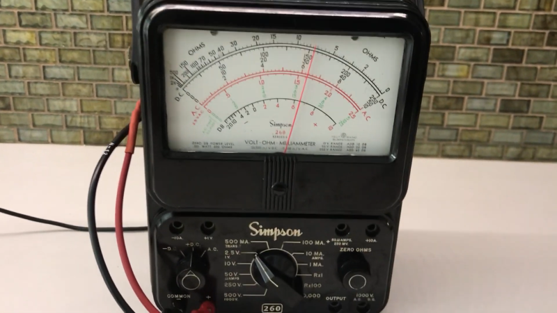
After hearing “is the internet up” one too many times, [whiskeytangohotel] decided to make a clearly visible indicator to show the status of the local uplink. He used his father’s old Simpson 260 VOM as a display, with its large analog indicator pointing at a steady value if the internet’s up, and wagging back and forth if there’s an outage. The exact value indicated is determined by the average ping time for a couple of different servers, so that you can also tell if the connection is slower than normal.
The ping times are measured by an ESP8266 connected to WiFi, which checks a predefined list of web servers and calculates the average ping time every fifteen seconds. An analog value in the 2.5 V range is then generated and measured by the meter. The smooth motion of an old analog meter stands in nice contrast to the modern-day problem of unstable WiFi.
While analog multimeters definitely have their uses, we’re the first to admit that our classic meters don’t see as much action as they could. Repurposing them as [whiskeytangohotel] did is a neat way of keeping those heirlooms around for the next generation. Of course, if you don’t have an analog multimeter, you could also use an analog clock for your ping meter.


“While analog multimeters definitely have their uses” [..] “The answer lies in being able to measure voltages that change.”
Absolutely. Digital multimeters are an alternative, no substitute by any means. If the thing we measure is “alive”, numbers are not enough. We need a scale. A digital multimeter with a graphical representation would be neat. Makes me wonder why none of the hackers made such a DMM yet.
Fluke meters have a bar graph at the bottom of the lcd to show scale/movement. Not quite the same thing as a full on analog meter movement though. But now that you mention it, I think it’s time to tweak my digital analog vu meter with physics project to turn it into a little multimeter lol. I can imagine making a little pcb for it with a tiny little manual mode rotary knob!
All three DMMs in view of me right now have a graphical representation, including one I bought in 1982. They update much faster than the numeric display: at least at 10Hz. A very useful adjunct to the numeric display. Pretty much standard on anything above zeroth-tier harbor freight grade stuff now.
My Simpson 467 from some time in the 1980s has a bar graph under the numerical readout.
https://www.simpson260.com/downloads/simpson_467_user_manual.pdf
Not sure what you are getting at here.
I do understand that analog meters can be good for measuring a noisy signal. The momentum of the needle acts as a low pass filter where the less significant digits on a digital meter might be changing so fast they are impossible to read. I do keep one around for that.
But it could be achieved pretty easily with a low pass filter, perhaps just a capacitor across the leads. Better and easier all sorts of solutions can be built into the software of the digital meter such as averaging, peak reading or even just freezing. That last one could be great when it is necessary to get leads into a location that is hard to reach and also watch the meter. Maybe a button that waits 5-10 seconds then simultaneously freezes the current reading and beeps.
What is meant by measuring a scale? You need not so much the number but a representation of where that number falls in a scale? Well that’s great if your scale is close to one of the meter. Otherwise I guess you could get there with an Op Amp or a voltage divider. Now I am imagining a more programmable digital meter. You could let the user set whatever range they expect the value to fall within and then display it as a bar graph, pie chart or whatever display they prefer. It could even go full circle as a picture of an analog needle!
Damnit! Now I’m going to be daydreaming about designing my own multimeter. It’s not like I don’t have too many projects floating around already!
Oh, that is what the parent post was describing isn’t it. I read before coffee and came away with something else.
“wagging back and forth if there’s an outage”
If it wagged back and forth more vigorously and hit the needle end stops, you’d have an audible indicator too!
You mean a “Googlecounter”?
Thank you, this made my day!
The sound the needle makes when it hits the end stop sounds like “ping”. Appropriate. The faster the wag, the louder the ping.
Neat project, neat implementation, useful… it checks a lot of good boxes. Particularly if the OP has no other use for the meter, I appreciate a project like this bringing it into meaningful, daily, use. It’s cool.
But the hole drilled in the back… that makes me cringe. Why ruin the housing on a perfectly good cabinet when the guts of the project could have been housed in an Altoid tin, plastic soap box, or similar container, and connected to the meter with banana leads?
By the way, “old” meter doesn’t necessarily mean worthless meter. Simpson still sells the 270 (not materially different than the 260) and it commands ~$300 at Newark.
The meter wasn’t “drilled”. One of the rubber stoppers in the battery cover was removed and that provides a hole to run the wires through. Look closely and you can see the other rubber stopper still in the batter cover.
If you want something a bit smaller, but still have that analogue feel, but with a digital backend, you can use something like the X27 stepper motor: https://forum.swmakers.org/viewtopic.php?f=9&t=2477 I have used the small driver board to plot my WiFi signal strength in and around my house. I managed 23m [~75.5′] and that was through 5 brick walls/metal framed doors etc.
A moving coil meter works against a spring and at some point there is a balance of the force or the moving coil and the force of the spring working against it. It was already spoken about the sensibility of a meter e.g.: 20000 Ohm/V. The moving coil meter is superior to show if e.g. a voltage goes up or down. Most technical work till about 1970th was done with this kind of meter. I like the simplicity of the electrical circuit, you can understand and repair a moving coil meter, anyway you can repair a digital meter too but it is more a black box affair. The moving coil meter is a combination of shunts in parallel for current and so called multiply resistors in series for voltage. The ohm circuit includes a battery and the meter works in a current circuit configuration. If you short the test probes the moving coil meter moves to full deflection and if you place a resistor in the circuit the deflection is less. Please note the ohm scale reads in the opposite direction.
For practical work you will decide what kind of meter you prefer. I would like to encourage you to think about the limits of a meter. This is true for every meter.