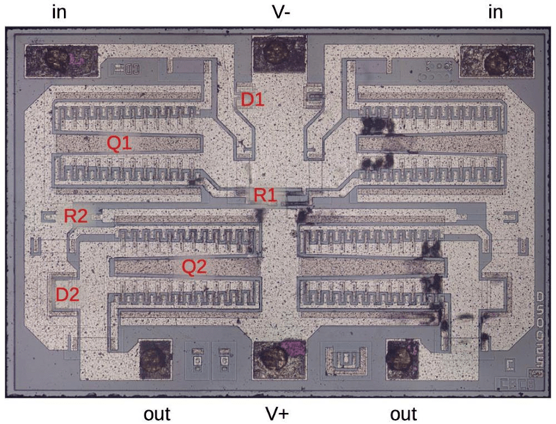
The Apple-I was a far cry from Apple’s later products. A $666 single-board computer, the product had some unique design features including using a shift register for video memory to save money. The shift registers of the day required high-current clock pulses that ranged from -11 to 5V and there was a DS0025 clock driver chip to handle the job. [Ken Shirriff] takes the unusual chip apart for us in a recent blog post.
The use of a shift register as memory isn’t a new idea. Really old computers like EDSAC used mercury delay lines as memory which was essentially a physical shift register. In those cases, the ALU and other processing only had to deal with a bit at a time, further simplifying things. For the Apple, there were seven shift registers to store 6-bits of display data and a cursor position. The 6 bits of character data drove — indirectly — a character generator ROM to convert the data into dots for the display.
Driving all those shift register flip flops requires a lot of clock current, so the DS0025 uses an unusual transistor design. There are 24 separate emitters in two groups. It acts like a large transistor, but you could also consider it as two 12-emitter transistors or 24 separate transistors in parallel. The metal wiring, interestingly enough, tapers because at the start of the conductor, the current for all 12 sub-transistors flows, but by the end, it is only the current for the last sub-transistor, so the conductor doesn’t have to be as wide. In addition, the two transistors have to have matched resistance which requires careful design so the transistors turn on at the same time.
The final result is an inverter that can provide 1.5 amps. This current helps overcome the relatively large capacitance in the shift register’s clock line. The clock rate was 1 MHz and the load capacitance was about 150 picofarads.
We enjoy [Ken’s] posts ranging from mysteries to space hardware. It is always interesting to see what is inside these devices or, at least, what was in the old devices we’ve all seen.


There was this time when long shift registers were the viable memory. Don Lancaster’s first TV Typewriter is said to have used it. The Apple I was a computer with an attached video terminal, so while it seems a bit late, probablyeasier than shift registers as main memory.
There were scan converters for Slow Scan TV about 1973 or 74. Convert the SSTV signal to digital and store in memory, where it could be played back at higher speed into a tv set or monitor. And they were viable because of surplus memory, which was probably long shift registers. I think it was, but it’s been almost fifty years. And I remember oneconverter stalli g when the surplus memory dried up.
This desktop calculator has a 40 foot coil of wire for delay line memory. https://www.oldcalculatormuseum.com/friden1160.html
Perhaps you may be able to help me. I have been looking for one early computer or calculator for oh about a millennium. I’m starting to think I am confusing parts of two different devices.
It was a 2 bit computer / calculator that had serial RAM which I thought was acoustic torsion wave along two wire coils like the one you mentioned. But maybe it was Serial RAM (Solid State). One serial path was the data path and the other was the instruction path, at least from memory.
I want to recreate something similar for it’s simplicity. I am just amazed at the idea of someone looking around the LAB for some memory and spots a roll of wire and says, oh I’ll just use that.
I have more or less given up on finding info so I have decided to do something similar with PAL Analogue delay lines made for PAL TV’s which were made of glass or crystal.
I have ordered one from the opposite side of the globe to experiment with but I am having trouble finding a source at a reasonable price. I could buy these new for $5 about three years ago. Now I only find ones (mostly second hand) for about $60 – $100.
Why is it -11 to 5v? The way I think of negative voltages is actually to shift them in my head so 0 to 11 to 16v, where 11 is being treated as “ground.” Were there components that needed 16 or 11 v? Was it to allow for analog reads? That seems pretty uncommon. I had an old Chris Craft and it was wired for I think 18 volts for the starter, which was strange but I was told it was an old naval standard? Just curious.
I have no idea, but Bil Herd talks of a “back bias generator” in his book, something to do with faster logic level transitions (from -2 V to +5 V for the 8563 in a circuit that was otherwise 0 to +5 V). Perhaps it’s related?
I don’t know the answer, but at the time “lots” of ICs needed.multiple voltages. I’m pretty sure the 8080 did. It was about the internel design, not a need for wide switching levels.
ECL had a very narrow distance between hi and lo, but generally ran off a negative voltage.
Early dynamic RAM needed a negative voltage too. If I remember, the lower density RAM in the Apple II needed a negative voltage, but as greater density dram came along, there were jumpers because the negative voltage not needed.
With time, a negative voltage faded, the push was to get rid of it, except for RS232. I think the Z80 didn’t need it, and the 8085 didn’t.
The old PMOS transistors in the shift registers required a 17-volt swing. The reason to make it -11V to 5V instead of, say, 0 to 17V, is for compatibility with regular TTL logic which uses 5V for a logical 1.