Noise is an annoying but unavoidable part of any engineering project. Fixing noise issues is hard enough, but even just measuring how much noise an amplifier adds to your signal is tricky without proper equipment like a spectrum analyzer. One other thing that makes noise measurements easier is a good, stable noise source that can serve as a reference: you first measure your amplifier without any input, and then measure it again with the noise source connected. Using a few simple formulas you can then calculate how much noise the amplifier produced.
Building a source that generates exactly the amount of noise that you want, no more and no less, is quite a challenge in itself. Several techniques exist, but [Wolfgang] over at the Electronic Projects for Fun blog decided to go for the classic method of using a vacuum diode. He describes the design and analysis of a noise source based on a 2D3B tube in a detailed article.
The tube in question is a special vacuum diode designed to be operated in saturation, meaning at a current high enough to draw away all the electrons generated by the hot filament. When running in this mode, the output current has a noise spectrum that is almost perfectly white, meaning its power level remains constant across the frequency band. [Wolfgang]’s measurements show a deviation of no more than 0.2 dB between 200 kHz and 200 MHz. This is about as close to perfect as you can get, and covers most of the frequency bands of interest to radio amateurs.
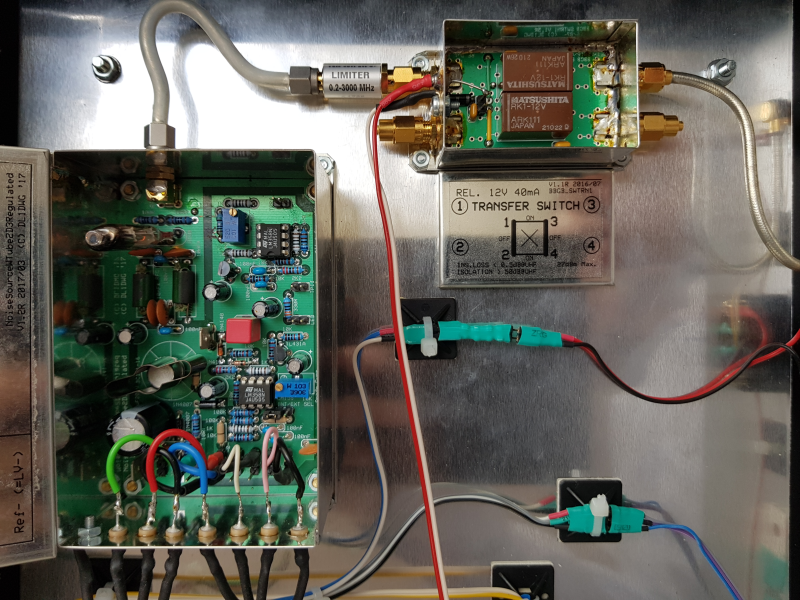
The whole project is built up inside a sturdy metal box, with extensive shielding and line filtering to keep undesired signals from contaminating the clean noise signal. A limiter is also an essential component: should the diode’s filament break, the limiter will prevent the sudden transient from reaching the spectrum analyzer and destroying its (very expensive) input stage.
[Wolfgang] has made a few other noise sources based on various components, which he compares on a separate page, although the 2D3B based one is by far the most stable. We’ve also featured a simple pink noise source, which is useful for audio measurement, as well as white noise sources designed to generate random numbers or simply to help you sleep.


Of course, noise is more significant the higher in frequency. I’m not sure 200MHz really covers the important range.
At lower frequencies, noise is more significant than what even a tube generates. But VHF and UHF, it matters more.
The higher the frequency the harder to get a decent tube, so certainly for 432MHz and up, most converters had the antenna feeding a diode mixer. Not good, but better than a tube rf stage.
In the late fifties, you needed exotic and expensive tubes to get low noise figures up there. The parametric amplifier was a significant improvement, but they were complicated and needed fine adjustment.
The Nuvistor made it simpler and cheaper, not the absolute lowest noise figure, but close to it.
Bipolar transistors started to bring good noise and gain, and slowly cheaper.
You needed a noise source to do the finicky adjustment to get best noise.
But slowly devices made it much easier, you still needed finicky adjustment for crucial use, but they gave you better than the past without the adjustment.
Parametric amplifiers were a big leap forward, but for hams, maybe about fifteen years of use, before easier devices came along.
Agreed. There is far more spectrum available to Hams above 200MHz, than, er.. “200MHz”.
Below 200MHz, (the 2m band possibly excepted for some) environmental, natural and especially man-made noise (from VDSL for example) is a far greater a problem these days, unless you live underground 100’s of miles from anywhere else.
No point having the ultimate sensitivity and low noise front end, if what background noise that comes down the wire is itself masking the signals you want.
RX “inter-modulation free dynamic range” is far more important these days below 200MHz, and becoming more important as 4G and 5G mobile services roll out, with the huge signals they radiated from cell sites, close in frequency to some GHz Ham bands.
73.
Even if you live super far from everyone else, galactic noise is really high around 100 MHz and still fairly significant at 200.
Mi Michael, hi other people that did comments,
I’m Wolfgang, the guy who made this part. First, thanks about your comments, they are most welcome.
To clarify, let me explain why I made this thing and how.
First, the purpose of the part was not only to be used in ratiometric (Y-method) noise figure measurements in radio amateur bands up to 200MHz, but also in measurement ultra low noise amplifiers (see my PhD thesis) that act as buffers for ultra low noise crystal oscillators. Atmospheric noise does not play any role here, stll we need accurate measurements.
If no ratiometric measurement is possible, flatness becomes an issue. Thats why I refrained from the usual Zener diode, or reverse BE junction noise generation circuits. The reason why noise is so nonuniform for those is the large variety of physical processes involved (avalanche processes, tunneling, crystal defects, surface impurities, ….) All of them have a different spectral distribution, and you can only measre the sum of them all, which gives a fairly fluctuating spectral density (even expensive commercial noise sources can have +/-1dB over the range).
The unique feature of saturated tube noise is the single physical mechanism that causes it, and the pleasant fact that the noise current is a direct function of the DC current (i.e., if we are in saturation, if no runtime effects occur, and we are out the the flicker corner). As shown, the saturated noise diodes work really well.
The limitations of the tube stuff are runtime effects for very high frequencies (with a 2D2S we can reach 400MHz, Rohde & Schwarz made an SKTU noise source up to 1GHz, but with much less flatness).
At low frequencies, lowpassed LSFR solutions work well, but I never got them as flat as the tube stuff (not only due to the sin(x)/x issue, but also due to other effects). I also tried a 500MHz ECL gate based solution that did not really work well.
Other candidates of white noise sources are hot resistors (lamps) or photodiodes. I tried both, but the tube stuff worked superior for both flatness and range. BTW, the NIST noise standards are also made of temperature controlled resistances (hot/cold sources). Details can be seen on my pages.
I agree that my prototype would not pass mass production requirements for VDE, UL and others. Its a decent lab prototype, not something intended for mass production. The essentials are there; if you need you can add all the necessary safety measures to make it foolproof. The shielding of my prototype is at least good enough not to display any disturbing spike between 200kHz and 200MHz, which I consider good enough for an ENR of just 7dB.
Again, thanks for the comments, time permitting I will add some new noise sources to my web.
Regards
Wolfgang
Thank you for documenting your work and your interesting results! You really increase the signal-to-noise ratio in the debate about noise generation.
I kind of wonder if you used a basic logic circuit to implement a LFSR (Linear Feedback Shift Register) to generate a pseudo-noise sequence of numbers and fed that directly into a DAC with a clock rate of maybe 400 MHz. How would that compare in terms of deviation to the vacuum diode and power usage for the same dynamic range (Which could be anywhere from 8-bit, ~48dB and up to168-bit!).
I actually did that some years ago, but I used a 1-bit DAC and much lower frequency of about 136kHz (IIRC), and I drove a cheap speaker via two simple AB-class amplifiers in push-pull configuration. It worked great in audio range, but was too loud for its intended use – to help baby fall asleep.
See the HP3722A for a practical implementation at lower frequencies (flat up 50KHz at the max 1MHz clock, one bit unfiltered flatish to 400 KHz or so). The low cutoff is provided by a sin(x)/x filter to keep the spectrum flat, as the spectrum from a one-bit LFSR follows (sin(x)/x)^2 envelope.
There was a writeup in the HP journal when it was released (1970-ish, IIRC) that goes into a lot of detail. Today, a solid two to three orders of magnitude improvement in bandwidth is certainly practical.
Yamakaja is just doing that, butnot with the terribly short (and linearly correlated) source that an LFSR is, but with a bunch of XOROSHIRO128+ pseudo-random number generators producing ca 1.8 Terabit/s of uniform uncorrelated randomness, feeding into Box-Muller algorithms to convert them to > 38·10⁹ Gaussian / Normally distributed random samples per second, for reproducible testing purposes.
This should run on any medium-beefy FPGA, but was specifically made for the Xilinx RFSoCs that contain a hardware LDPC decoder, as that’s what he puts the thus-generated noise through to test decoding / correction behaviour.
It’s essentially VHDL producing an AXI stream, so if you want to put this onto a DAC (e.g. the one your RFSoC came with, or your FMComms daugtherboard, or whatever), that should be easy enough.
It’s cool stuff: https://github.com/Yamakaja/boxmuller/tree/master/src
(so a “couple MHz” is really not the frontier here. He’s doing things in the range of multiple GHz of white noise per channel already.)
The author has spent a lot of time paying attention to detail with the constructions.
Colour coded heat shrink. An extra layer of heat shrink for strain relief. Cable tie blocks.
EMI suppression.
But there are some thinks I would like to mention in a positive way.
A lot of metals are pre-coated, sometimes with a clear acrylic paint, sometimes with a thin film of plastic, especially ferric metals (steel) as it rusts. A normal “nut and bolt” may not penetrate through this protective coating so you should always use “star” washers on earth points or points in the earth path to positively break through this coating.
All high voltage connections should be captive. There are captive “quick disconnect” connectors that look virtually the same as the normal ones but have a tab in the centre that you can press on to release it once it’s connected.
The high voltage supply to noise source should be separate and not cable tied to lower voltage writes. It shouldn’t make contact with lower voltage wires, it needs to be air gapped.
The heat shrink on the mains wiring is lacking. Two layers of over rated heat shrink (1000V+) would be better than what is here. Proper crimping with the expensive proper tool would be better.
The blue transformer is thermally fused ate 70 Degrees Celsius so that electro up against it is far too close if it’s going to get over 35 to 40 Celsius. I can’t see if the other transformer is thermally fused.
If the fuse blows or get jolted out of place then half the circuit is alive and half is dead and there’s a fuse floating around somewhere. Only one Mains fuse is best.
If you have exposed live parts inside then everything has to be bolted down and all wiring should be captive (can’t come apart) or at least be so hard to come apart that it can’t do so itself. Dupont connector come apart far too easy. The minium standard would be JST locking connectors. Even normal JST connectors may pass but definitely no Dupoint.
I hope all this doesn’t sound too negative. If your project was a piece of trash then I probably wouldn’t have commented.
However it really came together well and I love the mix of old and new technology.
I can see you put quite some effort into this so my comments are intended to be helpful rather than critical.
I acquired a bunch of N.O.S. K81A noise diodes some time ago and have a similar project on the to-do list.
Should work OK, but eats a lot more filament current (up to 2.5A). Maybe also the anode current stabilizer needs some adaptions due to different thermal constants.
I’m planing to adapt the tube into a modern realization of this:
https://www.analog.com/en/analog-dialogue/articles/dac-controls-precision-uhf-noise-level.html
The K81A is supposedly good up to ~300MHz.
Cool. Please tell me how it performs when done. Much luck !