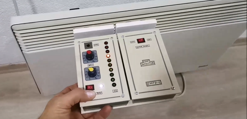
Electromagnetic interference problems can be a real headache to debug. If you need to prove what causes your WiFi to slow down or your digital TV signal to drop, then the ability to measure electromagnetic fields (EMF) can be a big help. Professional equipment is often very expensive, but building an EMF detector yourself is not even that difficult: just take a look at Arduino expert [Mirko Pavleski]’s convenient hand-held electromagnetic field detector.
The basic idea is quite simple: connect an antenna directly to an Arduino’s analog input and visualize the signal that it measures. Because the input of an ADC is high impedance, it is very sensitive to any stray currents that are picked up by the antenna. So sensitive in fact, that a resistor of a few mega-Ohms to ground is required to keep the sensor from triggering on any random kind of noise. [Mirko] made that resistance adjustable with a few knobs and switches so that the detector can be used in both quiet and noisy environments.
Making the whole device work reliably was an interesting exercise in electromagnetic engineering: in the first few iterations, the detector would trigger off its own LEDs and buzzer, trapping itself in a never-ending loop. [Mirko] solved this by encasing the Arduino inside a closed, grounded metal box with only the required wires sticking out. The antenna’s design was largely based on trial-and-error; the current setup with a 7 cm x 3 cm piece of aluminium sheet seemed to work well.
While this is not a calibrated professional-grade instrument, it should come in handy to find sources of interference, or even simply to locate hidden power cables. You can view this as a more advanced version of [Mirko]’s Junk Box EMF Detector; if you have a second Arduino lying around, you can use that one to generate interference instead.


Interesting… wonder if it can pulse another pin and radiate that, so you can make a nonlinear junction detector.
i remember my dad telling me, if you don’t connect the inputs on your quad gate 74xx logic chip, the unused ones will act like an amplifier hooked up to an antenna, wasting current switching on noise. i somehow failed to see this as the opportunity it was! :)
Not so much of a extra current draw if you leave the inputs floating but there is a good chance the input can rise above the maximum voltage burning up the IC.
It’s when the change in input causes a change in output of the gate that the higher current is drawn.
This is why when you look at the speed vs current graph of a CPU or MCU it’s almost linear.
Not your TTL 74xx, they were current source input devices and would mostly ignore unconnected inputs, but CMOS 74Cxx or 74HCxx, yes.
XOR gates can be used as very wide band amplifiers, modulators and demodulators. The odd thing is that to de-modulate you just modulate again.
They are like a wideband op-amp with an inverting input and another input that switches the mode of the inverting input to non-inverting.
Once you deal with biasing (CMOS is easier) Then you can surround an XOR with all your normal analogue circuitry and it will work that way.
I have a schematic of a purely analog sensor like this, but the arduino gives us an opportunity to focus on the “shape” of the field, or any kind of pulsed frequency if that’s available.
I once had a bad OLED hookup break the squelch on a radio scanner.
What about this but sending the output into an audio out jack? There are several such items on the market and people pay a pretty penny for them. I think the Soma ether laboratory is one.
Wow, measuring EMF with nothing more than an antenna, a filter, a DAC, and a digital signal processor!