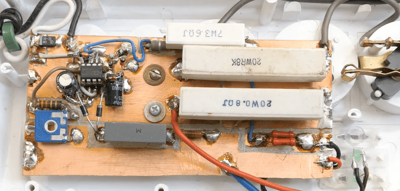
The idea behind watts seems deceptively simple. By definition, a watt is the amount of work done when one ampere of current flows between a potential of one volt. If you think about it, a watt is basically how much work is done by a 1V source across a 1Ω resistor. That’s easy to say, but how do you measure it in the real world? [DiodeGoneWild] has the answer in a recent video where he tears a few wattmeters open.
There are plenty of practical concerns. With AC, for example, the phase of the components matters. The first 11 minutes of the video are somewhat of a theory review, but then the cat intervenes and we get to see some actual hardware.
Inside the first wattmeter, he finds essentially the same circuit he was drawing at the start of the video, with some practical additions like range selection. The principle used is slightly different than the one he was drawing, but the core principle is the same: measure the voltage and the current to find the power.
We tend to be a little more cautious around main power, but unlike some other famous YouTubers, he manages not to shock himself or set any fires, at least on camera.
We marvel at the mechanical design of these meters and we also liked the homebrew power meter power strip. So if you like the theory, the teardowns, or a homebrew project, there’s something for you.
Measuring power at RF is a whole other science. Naturally, there are many ways to measure wattage, and not every instrument uses the same method.


There’s these Sunbeam powerstrips with a millionfold copies firmware/design FauxPaux being sold like everywhere. The all have the same autoswitch defect. The 4 slaves stay off till current drawn thru the front receps like they should. But they dont turn off auto like they should. Until the power to the strip itself switched off. DollarTree dumpin’ ’em rt now for $1.25. I opened one up to make all 6 receps always live (easy if you can solder rt) . discovered upon removal of the factory defective current sense/relay 1.25in sqr pc brd opened up enough room for the current transformer used in these cute little 6 line digital display ac pwr monitors available on Amazon for 20$. I used 150V 24ga rj11 4p4c wire to hardwire a 8 ft cord between the display and the strip itself. Built 5 of the ’em.
Has anyone figure out the case of those strips not working correctly? Would be funny if it was a little design mistake like the sensor being wired to also detect current going to the switched outlets. Or electromagnetic interference from the load wiring and/or relay tripping the sensor.