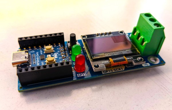
A PCB with an OLED display, a screw terminal block and a Raspberry Pi Zero board

Hackaday Prize 2023: Pi Pico Measures Volts, Amps And Watts

Measuring a voltage is pretty easy: just place your multimeter’s probes across the relevant pins and read the value. Probing currents is a bit trickier, since you need to open up the circuit and place your probes in series. Checking a circuit’s power consumption is the hardest, since you need to measure both voltage and current as well as multiply them at each moment in time. Fed up with having to hook up two multimeters and running a bunch of synchronized measurements, [Per-Simon Saal] built himself an automatic digital power meter.

The heart of this instrument is an INA219 chip, which can measure and digitize voltage and current simultaneously. It outputs the results through an I2C bus, which [Per-Simon] hooked up to a miniaturized version of the Raspberry Pi Pico called an RP2040-Zero. A screw terminal block is provided to connect the system to the device under test, while a 0.96″ OLED display shows the measured voltage, current and power.
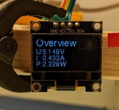
A small OLED display showing voltage, current and power measurementsThe maximum voltage that can be measured is 26 V, while the current range is determined by the shunt resistor mounted on the board. The default shunt is 0.1 Ω, resulting in a 3.2 A maximum current range, but you can get pretty much any range you want by simply mounting a different resistor and changing the software configuration. In addition to displaying the instantaneous values, the power meter can also keep a log of its measurements – very useful for debugging circuits that use more energy than expected or for measuring things like the capacity of a battery.

There are lots of ways to measure electric power, but they all boil down to multiplying current and voltage in some way. The multiplication was done magnetically in the old days, but modern meters like [Per-Simon]’s of course use digital systems. Some can even plug directly into a USB port. If you want to measure mains power, transformers are an essential component for safety reasons.

Low-Cost RF Power Sensor Gets All The Details Right

Dirty little secret time: although amateur radio operators talk a good game about relishing the technical challenge of building their own radio equipment, what’s really behind all the DIY gear is the fact that the really good stuff is just too expensive to buy.

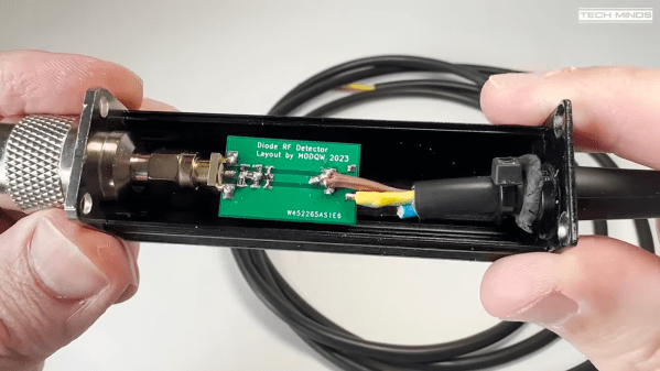
A case in point is this super-low-cost RF power sensor that [Tech Minds (M0DQW)] recently built. It’s based on a design by [DL5NEG] that uses a single Schottky diode and a handful of passive components. The design is simple, but as with all things RF, details count. Chief among these details is the physical layout of the PCB, which features a stripline of precise dimensions to keep the input impedance at the expected 50 ohms. Also important are the number and locations of the vias that stitch the ground planes together on the double-sided PCB.

While [Tech Minds]’ first pass at the sensor hewed closely to the original design and used a homebrew PCB, the sensor seemed like a great candidate for translating to a commercial PCB. This version proved to be just as effective as the original, with the voltage output lining up nicely with the original calibration curves generated by [DL5NEG]. The addition of a nice extruded aluminum case and an N-type RF input made for a very professional-looking tool, not to mention a useful one.

[Tech Minds] is lucky enough to live within view of QO-100, ham radio’s first geosynchronous satellite, so this sensor will be teamed up with an ADC and a Raspberry Pi to create a wattmeter with a graphical display for his 2.4-GHz satellite operations.

Continue reading “Low-Cost RF Power Sensor Gets All The Details Right”

What’s In A Wattmeter?

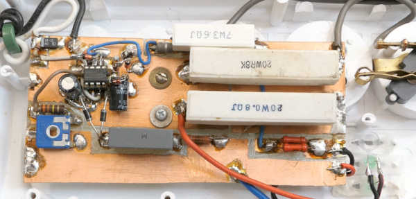
The idea behind watts seems deceptively simple. By definition, a watt is the amount of work done when one ampere of current flows between a potential of one volt. If you think about it, a watt is basically how much work is done by a 1V source across a 1Ω resistor. That’s easy to say, but how do you measure it in the real world? [DiodeGoneWild] has the answer in a recent video where he tears a few wattmeters open.

There are plenty of practical concerns.  With AC, for example, the phase of the components matters. The first 11 minutes of the video are somewhat of a theory review, but then the cat intervenes and we get to see some actual hardware.

Continue reading “What’s In A Wattmeter?”

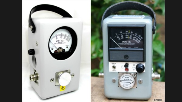
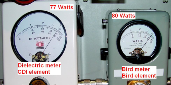
A Bird 43 wattmeter and its homebrew equivalent

Homebrew Wattmeter Pays Homage To Sturdy Original

If there’s one instrument that hams and other radio enthusiasts covet, it’s the venerable Bird 43 Thruline wattmeter. The useful RF tool has barely changed in the nearly 70 years since it was first introduced, and they’re built like a tank. This makes Bird meters highly desirable, and therefore quite expensive either brand new or on the swap-meet circuit.

But radio amateurs are nothing if not resourceful, and building a homebrew version of the Bird wattmeter (in Portuguese; Google translate tool at the bottom of the page) as Brazilian ham [Luciano Sturaro (PY2BBS)] did is a good way to get your hands on one. Granted, [Luciano] had a head start: a spare line set, which is the important bit from a Bird wattmeter. The machined metal part is in effect an air-insulated section of coaxial cable that the RF signal passes through on its way from transmitter to antenna. A “slug” is inserted into the cavity in the line set to sense the RF and couple it to the meter electronics; the slug can be rotated to measure RF traveling in either direction, allowing the user to determine how much RF is getting reflected by the antenna system.

[Luciano]’s version of the meter is faithful to the sturdy construction of the original, with a solid steel case that mimics its classic lines — the case even sports the same color scheme and stout leather carry handle. There are some changes to the electronics, and the meter movement itself is different from the original, but all in all, the “Buzz 50” looks fantastic. We especially love the detailed nameplate as an homage to Bird.

The thing about Bird — and Bird-like — meters is that the slugs are like potato chips; you can’t have just one. Curious as to how these slugs work? Check out this slug repair project.

[Featured image of Bird 43 Wattmeter: Martin RF Supply]

Thanks to [Niko Huenk] for the tip!

Old Wattmeter Uses Magnetics To Do The Math

Measuring power transfer through a circuit seems a simple task. Measure the current and voltage, do a little math courtesy of [Joule] and [Ohm], and you’ve got your answer. But what if you want to design an instrument that does the math automatically? And what if you had to do this strictly electromechanically?

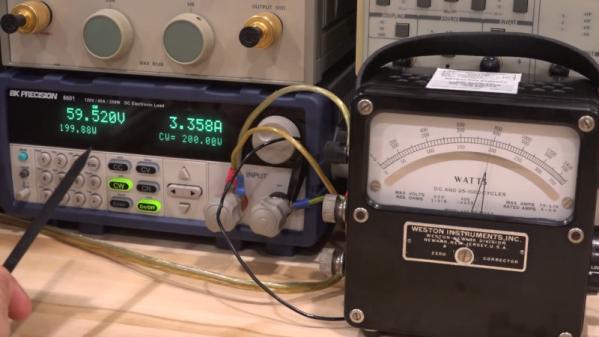
That’s the question [Shahriar] tackles in his teardown of an old lab-grade wattmeter. The video is somewhat of a departure for him, honestly; we’re used to seeing instruments come across his bench that would punch a seven-figure hole in one’s wallet if acquired new. These wattmeters are from Weston Instruments and are beautiful examples of sturdy, mid-century industrial design, and seem to have been in service until at least 2013. The heavy bakelite cases and sturdy binding posts for current and voltage inputs make it seem like the meters could laugh off a tumble to the floor.

But as [Shahriar] discovers upon teardown of a sacrificial meter, the electromechanical movement behind the instrument is quite delicate. The wattmeter uses a moving coil meter much like any other panel meter, but replaces the permanent magnet stator with a pair of coils. The voltage binding posts are connected to the fine wire of the moving coil through a series resistance, while the current is passed through the heavier windings of the stator coils. The two magnetic fields act together, multiplying the voltage by the current, and deflect a needle against a spring preload to indicate the power. It’s quite clever, and the inner workings are a joy to behold.

We just love looking inside old electronics, and moving coil meters especially. They’re great gadgets, and fun to repurpose, too.

Continue reading “Old Wattmeter Uses Magnetics To Do The Math”

The Early Bird Repairs A Slug

When faced with a problematic Bird slug, [Robert Meister] didn’t give up. He pecked away at the slug and brought us all along for the ride. If that sentence didn’t make sense to you, read on!

Anyone who’s been to a hamfest has seen a Bird meter. The Bird Model 43 watt meter is the defacto standard for measuring transmitter power in-line. Bird meters don’t just work from DC to light though. In fact, the model 43 itself is just a bit of transmission line and a meter movement.  The magic happens inside the swappable measurement element. These elements, affectionately called “slugs” are calibrated for a frequency band and power range. An example would be the model 4410-6, which works from 50 – 200 MHz, at up to 1 kW. Most hams have a collection of these slugs to go with the bands they transmit on.

[Robert]’s problem child was a model 100E element, good for 100 watts on 400 – 1000 MHz. The meter output seemed erratic though. A bit of troubleshooting with a second meter and a known good slug isolated the problem to the 100E. The problem was isolated to the slug, but how to fix it?

Slugs are sealed brass containers, each of which is calibrated to 5% accuracy at the factory. They are the closest thing you’ll find in the ham world to “no user serviceable parts inside”. Still, [Robert] had nothing to lose. He soaked the slug in a bit of Xylene solvent to loosen the glue holding the metal label on. Behind that were a painted screw and a hole for a calibration pot. We’re guessing the paint is Bird’s idea of tamper detection.

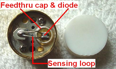
Pulling the screw out, and removing the nylon cover on the back of the slug revealed the real story. The slug contained a calibrated sensing loop, a diode, the calibration pot, and a terminating resistor. In [Robert]’s case, all he had to do was clean the contacts on the slug, and things worked fine.

For 11 years, anyway. After that, the slug started acting up again. Cleaning didn’t fix the problem this time. [Robert] ended up replacing the calibration potentiometer with a similar model from Digi-key. He re-calibrated the slug against his known good meter. It may not be a lab quality calibration, but this slug should be good for another few decades in his shack.

Measuring Spurious Emissions Of Cheap Handheld Transceivers

If you buy an amateur transceiver cheap enough to make a reasonable grab bag gift or stocking stuffer, you get what you pay for. And if this extensive analysis of cheap radios is any indication, you get a little more than you pay for in the spurious emissions department.

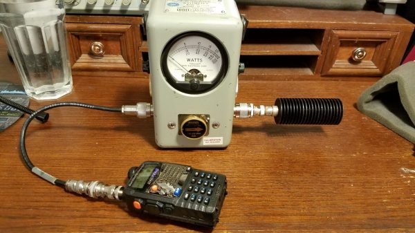
Amateur radio in the United States is regulated by the FCC’s Part 97 rules with special attention given to transmitter technical specifications in Subpart D. Spurious emissions need to be well below the mean power of the fundamental frequency of the transmitter, and [Megas3300] suspected that the readily available Baofeng UV-5RA dual-band transceiver was a little off spec. He put the $20 radio through a battery of tests using equipment that easily cost two orders of magnitude more than the test subject. Power output was verified with a wattmeter, proper attenuators were selected, and the output signal scanned with a spectrum analyzer. Careful measurements showed that some or all of the Baofeng’s harmonics were well above the FCC limits. [Megas3300] tested a few other radios that turned out to be mostly compliant, but however it all turned out, the test procedure is well documented and informative, and well worth a look.

The intended market for these radios is more the unlicensed crowd than the compliant ham, so it’s not surprising that they’d be out of spec. A ham might want to bring these rigs back into compliance with a low pass filter, for which purpose the RF Biscuit might prove useful.

[via r/AmateurRadio]