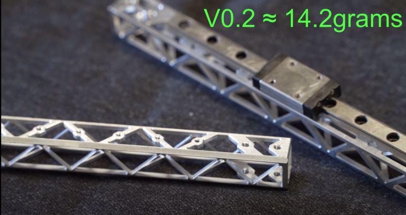
When it comes to 3D printing using fused deposition modeling (FDM) technology, there are two main groups of printers: Cartesian and CoreXY, with the latter being the domain of those who wish to get the fastest prints possible, courtesy of the much more nimble tool head configuration. Having less mass in the X/Y carriage assembly means that it can also move faster, which leads to CoreXY FDM enthusiasts to experiment with carbon fiber and a recent video by [PrimeSenator] in which an X-beam milled out of aluminium tube stock that weighs even less than a comparable carbon fiber tube is demonstrated.
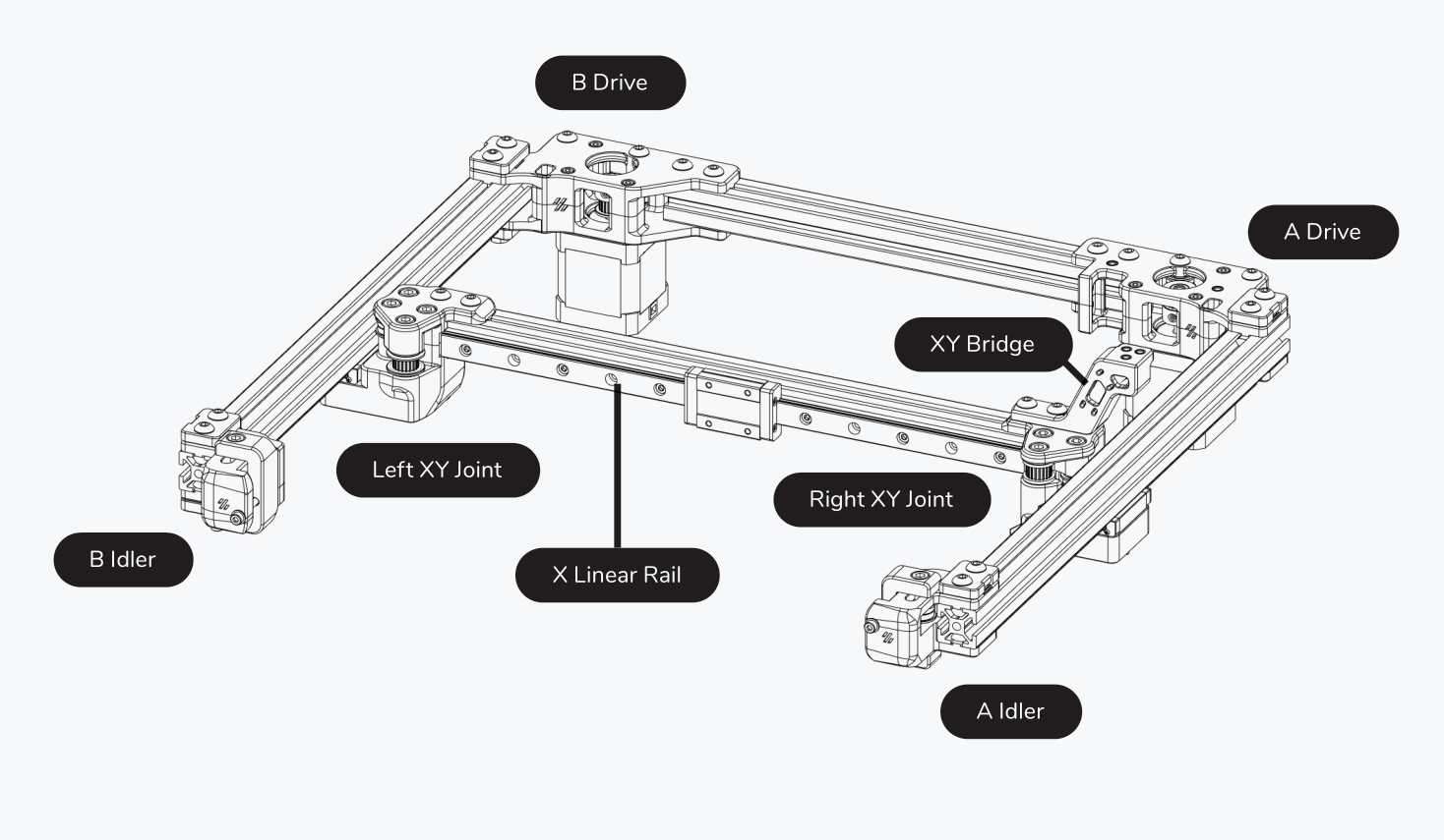
As the CoreXY FDM printer only moves in the Z-direction relative to the printing surface, the X/Y axes are directly controlled by belts and actuators. This means that the faster and more precise you can move the extruder head along the linear rails, the faster you can (theoretically) print. Ditching the heavier carbon fiber for these milled aluminium structures on a Voron Design CoreXY printer should mean less kinetic inertia, with the initial demonstrations showing positive results.
The interesting thing about this ‘speed printing’ community is that not only the raw printing speeds, but also that in theory CoreXY FDM printers are superior in terms of precision (resolution) and efficiency (e.g. build volume). All of which makes these printers worthy of a look next time one is shopping for an FDM-style printer.


Is that rigid enough?
Yes, of course, almost all of it is from linear rail ;)
Linear rails are intended to bend to the flatness of what they’re mounted to. That means if what they’re mounted to isn’t stiff enough the rail will bend what it’s mounted to. If it’s enough to be concerned about I don’t know, haven’t worked with linear rails before.
There’s some ultra keen Voron users who just use the linear rail without any other support, so this isn’t the least rigid system run on one of those machines with good results.
The CoreXY system moves it’s head in the X and Y directions. The Z axis is achieved by either moving the print bed or gantry. The advantage is in the reduced movement needed by the bed as Z movement is always small and comparatively infrequent.
That’s really pretty.
As another commenter has (sort-of) pointed out, the linear rails now start looking very heavy. I wonder if those could be made out of something lighter, like Boron? (what could possibly go wrong?)
Actually, I suspect that a better solution is to not separate the guide from the support. My cheap and ghastly printer uses a pair of steel rods as a guide and support, and I suspect that is competitive in mass with this design. (Absolutely not in precision and stiffness, though)
Hardened steel rods pocketed into diagonally opposite corners might work, though not with off-the-shelf recirculating ball guides.
Have some holes abrasive water jet cut down the middle of the rail to reduce weight. Make the back side the entry side so the natural spread of the jet will make a slight taper and non-sharp edge on the front side so the wipers on the slide (if so fitted) won’t catch and get cut.
They’re only hardened steel. Just mill them with carbide. I’ve machined parts from gauge pins, which are 52100 hardened bearing steel.
Not possible, because of internal stress in rail induced by inductive hardening applied when manufactured ( some chinesium mgn rails may not be hardened at all so those can be machined ) i had tryed lightening 15mm THK rail on edm wire cutter result was bent rail…
In fact it’s not even a proper support for a linear rail.
For steel rods embedded into aluminum, check Nadella rails, that’s basically the concept, but since the aluminum needs a big cross section to have some rigidity, they are heavy as hell.
FRANKE, german company make 4 side aluminium rails with embeded steel races – light and rigid, example:
ebay item no 154824180201 or direct link if HAD will allow:
https://www.ebay.com/itm/154824180201
A beam stiffness grows with the square of the area. Aluminum is a third of the weight and a third of the strength. Just a small increase in cross section more than makes up for the loss of material strength. Usually half the weight will give you a slightly stiffer beam.
With a surface grinder, one could probably reduce the rail to an H profile, with the bridge between the side walls located between the contact plane of the balls (they’re probably 4-point contacts, but you get the point).
TIL: there are also titanium (alloy) extrusions: https://www.plymouth.com/products/net-and-near-net-shapes/
but you have to ask for the price.
Malwarebytes blocked that site because it says it might contain a trojan lol
Then Plymouth Tube Company USA has a problem, lol. Checked with virustotal, an all tests report clean except for “Yandex Safebrowsing” which thinks it contains malware.
Meanwhile, here’s a video of the extrusion process: https://www.youtube.com/watch?v=P0vE1oJNAjM
Very nice work! And out of hardware-store aluminum extrusion, plus a lot of quality CNC time.
Making the rails out of boron is brilliant, though. B/c then you’d have a boron Voron.
I also feel like the linear rails are looking heavy, and I like the idea of integrating steel guide rails. I mean, this is for a 3DP, not a mill — you could probably go pretty thin. Or use urethane/plastic wheels and run them straight on the aluminum?
Let’s hope nobody tries to make one out of Be ;)
There’s an interesting remark in the video comments about using carbon fiber. Now imagine a 5-6 axis machine that can overwrap a 3D printed mandrel in optimized directions. Cannot find much on CF winding projects.. this one maybe? https://www.youtube.com/watch?v=VEGMEFynPKs
Haven’t looked into this too much, but is the rail itself not strong enough? Do you actually need more that just a corner bracket to attach the rail to the side rails?
My first thought was halving the weight again by milling the triangles out of angle stock instead of tubing, but you have a point there…
Angle stock tends not to be very torsionally rigid in my experience.
Does it need that much torsional rigidity in this application? If so, braces could be installed “inside” the angle, perhaps held on using the screws used for the rails.
FYI: I found this video useful for rules of thumb on different structural shapes:
https://youtu.be/cgLnADEfm6E
I wonder if the VZbot guys or Voron guys came up with this first.
I guess if you don’t have a mill you could go nuts with a drill press, just drill large and small size holes and get fairly close to that.
A strange obsession for sure (“but why?” is never a valid question on HaD) but this could be optimized further (lighter) by utilizing a genetic algorithm to evolve the most efficient part. It would likely have even better results if you used solid feedstock and allowed it to be cut once on the X axis and once in Y axis.
I know bio-evolutionary technique is in fashion right now, but I’d go for fractal because it seems more sceincy and didn’t rely on iterative guessing :-P … that’s probably oldschool now, what do we call it, 90s fractalpunk ? :-D
I think going to solid feedstock the cost would far outweigh any of the benefits. You’re already milling away a large fraction of material, that’d make it even more.
Why assume a move to solid stock? Interesting optimization methods can still be applied to square tube.
Because Gravis suggested it? There were multiple sentences in that comment. :)
Also with regard to optimizing the square tube I think you’d actually end up with extremely little change in terms of mass. The triangles in the truss are already optimal, and the mount point stuff is more manufacturability. If you convert it to asking “what’s the optimal design in this application” (so, like, a full structural analysis of a 3D printer or something) then yeah, sure you can probably find places to cut weight.
I mean… it’s a truss.
A more achievable way to get optimization would be topological optimization. I’ve only played around with it in SolidWorks, but I think there are plugins to do it with FreeCAD.
After watching the video, there are some (relatively) low-hanging fruit for further optimization (though, even as a Core-XY machine owner, I don’t personally see the interest of this rabbit-hole):
-moving the rail closer to the side for better stiffness (currently, it will experience the macro deflection of the beam as well as the deflection of the struts its mounted on)
-classical truss beam optimizations: the trusses aren’t optimally designed, and even without going through the effort of implementing a cutting-edge optimization tool, truss beam design is an extremely well-developed field. He could probably cut the weight by another third without any penalty to stiffness after reading a bridge design textbook
Though, realistically, it’s already so light (and looks to be stiff enough to not significantly affect repeatability), that I don’t see the point of further improvements, at least not without addressing the weight of the rail first (as others have brought up)
“He could probably cut the weight by another third without any penalty to stiffness after reading a bridge design textbook”
Cut the *weight*? I’d agree he could probably increase the *strength*, but where would the extra weight come from? The majority of the remaining metal is there for the rail, not the truss.
Use aluminum screws used by RC enthusiast and mill the linear rails that would shave off a few more grams.
Oh by the way, it was discovered on a car forum a decade or so back that filling rocker panels with expanding foam tremoundously improved rigidity on some vehicles (Improving handling etc)
Therefore it might be an idea to try very light thinwall tube, possibly needing plates for mountings welded, brazed, soldered, sweated, on or similar, that has been filled with expanding foam.
It shouuuuullllld be obvious, but you wanna do any burny, melty, heaty, warmy, hot type operations before foam filling of course.
Aerospace does similar with honeycomb composite panels. Extremely thin CFRP or aluminum outer skin with a typically kevlar honeycomb between. Extremely stiff, extremely lightweight.
I don’t think thin-walled tube would be the way to go. I’ve never been a huge fan of injection-molded CFRP (it loses much of the benefit of UD CFRP, which is the long average strand length that lends it so much of its strength), and aluminum would typically not be sold thin enough to get significant weight savings. I suppose one could mill it extremely thin, but chatter would probably make it unfeasible to mill it thin enough.
If I were to go this direction, I would instead get a thin sheet of bidirectional CFRP off of one’s favorite budget goods website, cut it to size and bond it to some closed-cell foam, maybe wrapping it with a layer of CFRP or fiberglass. This would give it great rigidity in the motion and head support axes, and the wrap would give it just enough torsional rigidity to resist the moment from any small overhang from the printing head.
Filling rocker panels with foam also tremendously increases hidden rust, and often flammability too.
In a pinch, once printed some rails from pla
I applaud the effort and ingenuity but I can’t help feeling that trying to squeeze the last bit out of a design that simply cannot be future proof is wasted effort. The only possible way forward is to make 3d printing massively parallel to reduce print times and once someone cracks that all these designs won’t be able to compete.
Nice! I’ve been wanting mill a linear rail support for my SolidCore printer build.
Why not start with a CF tube ?
I can think of a few reasons, one being cutting CF isn’t nice at all.
But I think structurally it might be a bigger concern – the strength of carbon fibre is largely in those long entirely encapsulated fibre, go cutting through them all to make it lighter and you don’t really have useful reinforcement the same way – now creating a CF ‘tube’ or truss with the weave where you need it, running in the right directions would be rather impressive, and as they have a CNC mill they could cut out a squash mold for doing so.
Trying to find the compromise between doing what you said, which is the optimal approach, and having an easy to diy method is one of the arguments for using what is sometimes called forged carbon fiber.
But I think that I find the idea of trying this same basic machined shape, just in a Zr alloyed magnesium (or some other really high strength Mg alloy). The good magnesium alloys have an even higher strength to weight ratio than aluminum. If I remember correctly, they are still not quite as “strong” as carbon fiber, but they are significantly stiffer, which I would think would make a difference in this application.
I’m skeptical that this really “weighs even less than a comparable carbon fiber tube” – I mean, that’s kinda the whole point of carbon fibre, it’s stronger and lighter than materials like aluminium.
We used some CF tubing with (literally) paper-thin walls on a project and it was miles stronger than a much thicker & heavier equivalent in aluminium no matter how many speed holes you cared to add to it.
Feels to me like this is either “because I could”, “because it looks cool”, perhaps “because I can’t afford a CF tube” or maybe “because we’re comparing this to a CF tube of vastly different / inappropriate spec”.
Define ‘stronger’ – it is so situational as a word, are you really after stiffness, ultimate yield strength, etc?
I suspect this will be better than similarly heavy off the shelf CF tube for this role, even more so if the truss layout is better optimised – what extra light CF tube will do is fail and crack somewhere very suddenly – probably at a mounting hole where the weave has been drilled out, not to mention how much surface structural damage or padding work, which adds mass, did you do to a CF tube to make the linear rail surface flat enough – so you have to operate the machine with a healthy safety margin to not get that brittle failure, the Aluminium on the other hand will deform temporarily a little elastically when highly loaded by a really fast machine move which will perhaps show up in the finished parts off the machine but its under no threat of destroying itself with no warning. That rapid failure mode of CF vs the forgiving nature of the AL means even if the CF structure could run a tiny bit faster you wouldn’t actually get it there in practice as its flying too close to the sun.
Now a carbon fibre truss/tube like object designed specifically for the role, with selective weave directions etc vs this Aluminum truss is a very different thing as suddenly you are doing in the CF what this has done to the Aluminum and removing the excess mass without changing the structures mechanical properties in the important directions meaningfully.
It would be interesting to see it milled out of a magnesium square tube. Magnesium is lighter but also stronger. It also absorbs more vibrations. Magnesium would be easier to work with than CF. Yes it is expensive but you are already sinking a crazy amount into the CNC machining. I would be interested in seeing what could be done with linear guide rather then having a solid steel rail. Yeah the linear rail will flex to the mount but you can also optimize the rail if you want to flatten it so that it doesn’t have to bend to the mount.
Why mill all the way through rather than just strategically lighten the load while leaving a skin to enhance the tensile properties?
No one here is talking about the significant increase in vibrations (frequency) with this installed over the “prescribed” material. Once Voron users started seeing freq charts, people seem to have started looking away from this option.