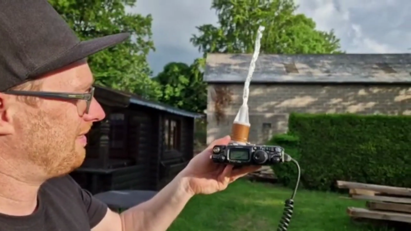
[David], DL1DN, is an Amateur Radio enthusiast with a penchant for low-power (QRP) portable operations. Recently he was out and about, and found that 10 m propagation was wide open. Not discouraged by having forgotten his antenna, he kludges up a makeshift one using a 20 cm length of aluminum foil (see video demonstration below the break). [David] wasn’t completely unprepared, as he did have the loading coil for his portable 20 m antenna, but was missing the telescoping whip. He calculated the whip length should be around 20 cm for 10 m operation, and crinkles up a sheet of foil the approximate length. He tunes it to length by rolling the tip to shorten the “whip” until he gets an SWR minimum.
What are some unusual items you’ve used as makeshift antennas? Let us know in the comments below. Thanks to [mister35mm] for submitting this to our tip line.


10m is the wavelength, remember the equation c = f * L … L is normally lambda for wavelength. Ah wait, see if this will paste..
c = fλ
So of course, f=c/λ
but if you want answer in mhz just sub 300 for speed of light c and you get 30Mhz. Which is close, but 10m band starts near 28Mhz in real life and they didn’t wanna call it some non decade decimal of a mess so round down.
The bands were bigger, well after they were cut. I think it was the Radio Act of1912 that sent hams to the “useless” frequencies above about 2 MHz. In 1921, there were tests to show shortwave was useful. I’m not sure when the change from “everything above about 2MHz” to distinct hambands, but obviously others realize the value. But the hambands were wider, and smaller after WWII. So the metre designations were perhaps accuturate for the bands at that point, and it was easier to stick with it.
That’s right, I think. The 11m band (yes, the CB band) originally was part of the 10m amateur band. That’s one of the reasons very old amateur radios have the 11m band located on the switch, for example. Or why the scale went down to 26/27MHz. That was later removed.
Of course, there’s also another reason why the 11m band can still (or rather: again) be selected on amateur radio gears.. Makers of amateur transceivers realized that they can sell (way) more units, if they attract CBers, as well.
Likewise, makers of CB radios made “export” radios that had high power and could transmit in 10m band, too. Either by factory default or through simple modifications.
Officially, this optional feature was meant for licensed hams who used the “CB” radios as amateur radios on 10m. In reality, of course, it was a legal loop hole used by manufacturers to legally sell illegal radios. Or so I heard.
That being said, some poorer amateurs did likely benefit from this, as well. CB radios are readily available, comparably cheap, based on current technology etc. Compare this to an old FT-817 from the Windows 95 days to a CB radio with SSB/AM/FM and an OLED screen, and you’ll understand that this can be comforting. 😉 Vy73, Joshua
And then there’s transverter use. I almost forgot about it.
In Europe, the 2m band is 2Mhz wide (144-146 MHz).
But in USA, which is always bigger, the 2m band is 4MHz wide (144-148 MHz).
So in order to properly convert or transvert, a 4MHz range is needed.
Otherwise, a high/low switch must be used on the transverter/converter to select the upper/lower 2MHz.
Amateur shortwave radios that can receive/send from 26-30MHz or 28-32MHz can fully use such a converter/transverter.
A buddy wanted to connect to the free wi-fi down the street from his (pay for wi-fi) hotel room. He had a wi-fi USB dongle and a USB male-to-female extension cord. A quick trip to the hotel kitchen got him a free piece of aluminum foil. He pressed the foil into the in-room ice bucket, put his dongle inside and pointed the open end down the block to connect to the coffee shop nearby.
You can also try foil lined chip bags and juice cartons. The thicker foil of pie plates is quite amenable to rubbing over your knee into a fair approxmation of a parabola.
I am afraid I have quite littered the world with temporary TV antennas caused by stripping dollar store, corner store, bodega etc purchased RG 59 hookup cables, that I stripped back about 6″ and spread to a dipole.. preferring antenna on the TV to pay per view. (Okay. I’ve done it 3 times maybe, there’s not a pile of RWed cables the size of a tire mountain.)
Purpose of a tuned antenna is to increase efficiency (thus signal strength). While a 1:1 ratio is very good, you can obtain useable signal with a fractional/multiple length. In this case, the “ideal” antenna would be 10 meters (about 400 inches) long. A 5-meter/200-inch antenna would work, but not as well. 100-inch, 50-inch, 25-inch, 12 1/2-inch, etc. There are lots of tricks to “fool” the radio into thinking it’s working with a different length (loaded coil, simple capacitor circuits, taps, etc.). A bigger antenna that does not match the frequency is not as good as a smaller antenna that is tuned properly. Thus the user’s SWR bridge efforts (a test meter that shows how much energy is wasted).
“Purpose of a tuned antenna is to increase efficiency (thus signal strength). While a 1:1 ratio is very good, you can obtain useable signal with a fractional/multiple length”
Well, yes. But tuning/matching alone doesn’t make a good antenna. Someone can match a light bulb with an 1:1 SWR, but that won’t be a good aerial still. 😉
“In this case, the “ideal” antenna would be 10 meters (about 400 inches) long. ”
I noticed your quotation marks! 😁
Well, full wave antennas are a strange beast.
They have a very high impedance, for example.
Most people will use half wave antennas or lower in practice.
“A bigger antenna that does not match the frequency is not as good as a smaller antenna that is tuned properly. ”
Generally, yes. However, a big antenna takes up more physical room, so there’s a chance it had “better sight” to another radio station.
Or in other words, a good antenna in the cellar is worse than a mediocre antenna on the roof.
Also, antennas don’t necessarily need to be in resonance to function.
Long wire antennas can still be used for reception, for example.
And then there’s the radiation pattern.
Different antenna types have different patterns.
That’s why some are good for local talk, some for distant communication (DX).
The height also plays a role here.
“Thus the user’s SWR bridge efforts (a test meter that shows how much energy is wasted).”
Yes, many operators keep an eye at best SWR. That’s also good in case of RFI and sheet waves. However, some oldtimers may not tune for best SWR, but highest radiation. That requires an RF meter or an SWR bridge with its own antenna, located at a distance slto the antenna.
Alternatively, some crystal radio with a digital multimeter or an analogue micro Ampère meter (100 micro amperes) can be used.
Oh, and then there’s the lenght of the coaxial cable.
It plays a role for SWR. If the length is unlucky chosen, the SWR will be bad no matter what.
Also happens with cheap 50Ohms cable with reflections inside. Like, network cables. NanoVNA etc. can display those.
Ideal, the coaxial cable should be half the wavelength or a multiple of it (integer). Plus the velocity factor. RG58 has 0,66 for example.
However, RG58 is very dated. Man made noise crawls into it all the time. Let’s use something else, with a very high shielding level and low loss.
Anyway, that’s not meant as a critique whatsoever. I just replied what came to mind. Vy73 Joshua! 🙂
Meh. If it’s under 5:1, call CQ.
I’ve made (I’ll be it, short range) cw contacts with a light bulbs for a radiator. My coming up in ham radio, I ran with a wild bunch. Not sure what was crazier / more amusing – stringing twin lead and an end fed dipole out the door of a motel room at Dayton, loading up an aluminum light pole in a parking lot, or using a ~1.5m telescoping whip attached to a Ten Tec r4020 (with a 10′ counterpoise) from a table inside a dairy queen making contacts from PA to MO. Radio can be wild stuff.
Roger, Old Man.
Just make a dipole with the foil