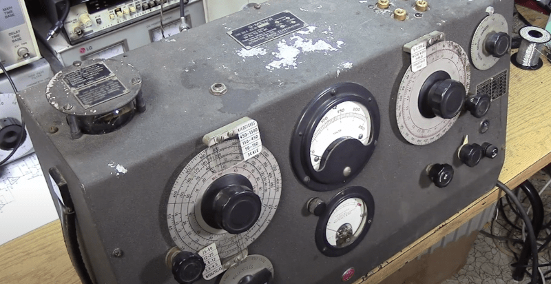
If you’ve ever dealt with RF circuits, you probably have run into Q — a dimensionless number that indicates the ratio of reactance to resistance. If you ever wanted to measure Q, you could do worse than pick up a vintage Boonton 160A Q meter. [Mikrowave1] did just that and shows us how it works in the video below.
Most often, the Q is of interest in an inductor. A perfect inductor would have zero resistance and be all reactance. If you could find one of those, it would have an infinite Q because you divide the reactance by the resistance. Of course, those inductors don’t exist. You can also apply Q to any circuit with reactance and the video talks about how to interpret Q for tuned circuits. You can also think of the Q number as the ratio of frequency to bandwidth or the dampening in an oscillator. A versatile measurement, indeed.
It sounds as though you could just measure the resistance of a coil and use that to compute Q. But you really need to know the total loss, and that’s not all due to resistance. A meter like the 160A uses a signal generator and measures the loss through the circuit.
The best part of the video is the teardown, though. This old tube gear is oddly beautiful in a strange sort of way. A real contrast to the miniaturized circuits of today. The Q meter is one of those nearly forgotten pieces of gear, like a grid dip oscillator. If you need to wind your own coils, by the way, you could do worse than see how [JohnAudioTech] does it.


A superconducting coil, should measure pretty high on that Q-meter, n’est-ce-pas?
Not as much as you’d think. Superconductivity is very much a low frequency phenomenon. Once you up the frequency you start dragging magnetic vortices back and forth along the surface of the conductor as the field fluctuates. Since that requires the application of work the losses increase with frequency and the Q decreases accordingly.
Damping not dampening. You are not making anything wet!
I don’t think it’s “forgotten” like the grid dip oscillator. But most people don’t need to measure Q. I can’t think of a modern version. The GDO had a lot of functions when test equipment was rare. Other things have taken over as test equipment became cheaper.
Or let’s simply build quality coils again. Like hand-woven air-core coils, spider web coils (2D), comb coils (3D) etc.
in short, shoot those overrated Amidon coils to the stars and use coils with a decent amount of quality factor.
We’re living in amazing times, because we still remember the early days of radio technology
and have access to modern manufacturing processes and digital technology.
This puts us in the conveniant situation of perfecting them both by combining them! ^_^
With a 3D printer, we could print out forms of spider web coils or tools for making them easily.
I’m sincere. I’ve build many spider web coils myself and their Q
was noticable better than that of air coils or ferrite coils.
So please every, give it a try, at least. Old fashioned coils can be great, still.
And making them is an art, a craftmans ship. So it’s definitely worth trying out.
The variometer coil, for example, is *very* fascinating. It deserves a second chance, too.
Links:
http://www.jogis-roehrenbude.de/Bastelschule/Vario-Detektor.htm
https://www.instructables.com/Spider-Web-Coil/
https://www.welt-der-alten-radios.de/detektor-spider-183.html
https://www.radiomuseum.org/forum/beautiful_coils.html
Interesting that parasitic capacitance reduces Q.
I wonder if anyone has used spider windings in a Tesla coil?
“Booton”, is that some knock off Chinese junk?
Oh, you kids…I bet you think Hewlett Packard only made printers and laptops :-)
I think his nitpick was with “Booton” when it should be “Boonton”. I’m taking his word that there’s a typo.
Everyone knows HP started in a garage making an audio oscillator with a light bulb.
Yeah, the typo is in the first link.
I do like old skool gear, but my space is limited, so it is mostly smaller stuff (e.g. Bakelite meters, Heathkit GDO, HP 200C or D,
vacuum tube tester, Hickok O-scope and sig gen)
Gimme that old-time ham kit
Yeah — classic piece of gear. Very old skool look. It’s as much a piece of art as a piece of test equipment.
Looks like a prop from M.A.S.H.
Could also probably do double-duty as a battering ram or a boat anchor
There is a thread on groups.io in the Test Equipment Design and Construction group about designing and building a Q-meter.
It’s above my pay-grade so I’m just waiting for the design to reach a point that it can be relatively easily replicated to build my own.
This parameter is relevant in power system engineering, but is called the X to R ratio. It impacts the performance of the system under transient (especially fault) conditions, and needs to be considered when assessing capability of equipment. Particularly circuit breakers.
Silly me: I thought all these years that Q affected bandwidth
Well, Q certainly affected the crew of the Enterprise D!
B^)
Depending on whether you are serious, yes, it does. Another way to define Q is the resonant frequency divided by the bandwidth. A higher Q means a narrower bandwidth. Maybe ‘more selective’ depending on what you are looking for.
Yet another way to define it is energy stored in a oscillator divided by the energy dissipated per cycle. So, less energy being dissipated means a higher Q. A higher Q oscillator will keep ringing for a longer period of time after the driving signal is removed.
(A very high Q oscillator will also take a long time to really get up and fully oscillating as you also can not shove much energy into it each cycle. You might find that you have to buffer up stuff you want to transmit as you are waiting for the oscillator to get fully going. Don’t ask me how I know this.)
I designed a Q meter and it appeared in an article in the Australian Silicon Chip magazine, January 2023.
I am currently working on an improved design that uses a scanning signal generator and peak voltage detector to automate the measurement. Just connect the coil and press start and within 10 seconds it will find the peak frequency. Q measurement is from 5 to 300 and the frequency range is from 90MHz to 100 kHz the high and low values may be selected. It gives a readout of Q, frequency and inductance on an LCD screen and runs off three AA cells. The design is near complete and it will feature in Silicon Chip later this year.
I have a Meguro Q meter that dates from 1968. It also came with a box of standard inductors. It still works perfectly.