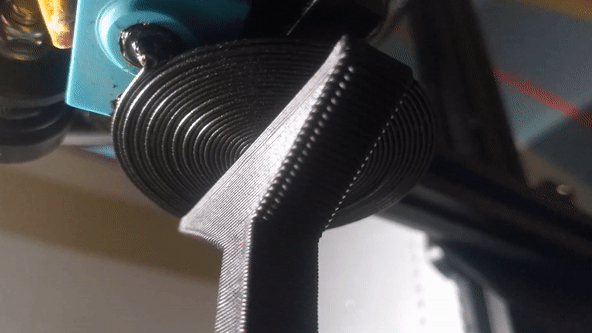
Interested in the new hotness of printing previously-impossible overhangs? You can now integrate Arc Overhangs into PrusaSlicer and give it a shot for yourself. Arc overhangs is a method of laying filament into a pattern of blossoming concentric rings instead of stringing filament bridges over empty space (or over supports).
These arcs are remarkably stable, and result in the ability to print overhangs that need to be seen to be believed. We covered this clever technique in the past and there are now two ways for the curious hacker to try it out with a minimum of hassle: either run the Python script on a G-code file via the command line, or integrate the functionality into PrusaSlicer directly by adding it as an automatic post-processing script. The project’s GitHub repository has directions for both methods.
Here’s how it works: the script looks for layers with a “bridge infill” tag (which PrusaSlicer helpfully creates) and replaces that G-code with that for arc overhangs. It is still a work in progress, so keep a few things in mind for best results. Arc overhangs generally work best when the extruded plastic cools as fast as possible. So it is recommended to extrude at the lowest reliable temperature, slowly, and with maximum cooling. It’s not fast, but it’s said to be faster than wrestling with supports and their removal.
A few things could use improvement. Currently the biggest issue is warping of the arc overhangs when new layers get printed on top of them. Do you have a solution or suggestion? Don’t keep it to yourself; discuss in the comments, or consider getting involved in the project.


A suggestion is to after have the arch done, make next layer in another direction, like straight over or diagonally over the arch layer. Might help?
I feel like this sort of overhang doesn’t necessarily need to be an arc shape, but I’m not well-versed enough in slicer development to know if I’m wrong or not.
There’s a video by CNC Kitchen explaining more, but the advantage of this trick is printing flat (90 degree) overhangs without support towers, a huge step up from what most printers can do (80 degrees off vertical is the normal maximum without supports in PLA in my experence).
I get that, but why does it need to be circular? Could you do concentric squares or triangles? The corners would probably require some additional positioning/extrusion math, but it seems worth it.
it does not need to be arc and it’s actualy suboptimal. should use offseted contours of desired shape instead. for example filling square with arcs like this creates tiny arcs in corner, which do not tend to stick well to the rest.
I think that the idea is to ensure that no matter the printer precision, the new filament will be “pushed against” the previous pass. If you do it straight, you must ensure that the printer header moves very close to the previous pass. Instead, using circles, you can be even a little bit separated and it doesn’t matter, because it will end being stick to the previous pass.
It is circular so there is a minimal amount of drooping and dribble – it is well anchored into the main body and as the plastic cools and shrinks that little bit it is compressing itself into the previous arc as it goes – with straight line on straight line approach only the layer to layer type bond that is usually very much weaker is involved and as it cools it probably wants to warp away from the rest of the model if anything.
Technically, any space filling curve would do (Hilbert Curve, Spiral, …). However, since the technique is new, and is more like a hack that’s postprocessing the slicer’s output, it’s much easier mathematically to use concentric circles to fill an area, since it only involve solving quadratic equations.
Also, any right angle in the space filling curve means more time spent by the extruder on that spatial point, so an hotter spot to cool to avoid wrapping.
I guess if the algorithm was integrated in the slicer, then the origin of the curve could be inside the part (instead of only on the “bridge”) making it more strongly anchored.
Also, to avoid wrapping, it would mean modeling the gravity force on molten and not-molten-but-soft elastic plastic to counteract it while extruding in mid-air. It’s not infeasible but I think it’s more trial and error here.
The molten filament coming out of the nozzle is semi-plastic/semi-elastic. The point of the concentric circles is to pull the fresh string towards the center of the circle. This keeps tension in the new arc and pulls it against the previous arc inside. The smaller the radius of the arc, the higher the tension will be, and straight pieces would be laid without tension towards the previous line.
Actually, I don’t think that’s true. I don’t think this will work with any space filling curve. I think this new overhang trick works because it’s arcs, and there are no sharp corners. The problem with 90 degree corners is, you’ll have a small section that isn’t connected to the line next to it, and that will allow the corner to move up or down (due to gravity or to shrinkage)
That might sound like a small “error”, but it compounds so that error gets bigger and bigger with each line. Causing the whole method to fail.
Then again, I might be wrong. I haven’t worked with 3D printers for quite a while now.
I believe it works because as the filament cools, the shrinkage puts it in tension, pulling it into the arc next to it. I believe it could work with other arcs like parabolics, too.
I feel like arcs are actually the most suited shape for this, and it is for the same reason bridge overhang works even thought not many people seem to get it : Filament contracts when cooling down, so there’s actually tension that pulls the string of filament “up” in a regular bridge, and against the previous layer in the case in arc overhangs. As soon as you try this with any non-convex part of a shape, the tension works the opposite direction and the filament doesn’t stick to the previous layer.
It’s very easy to demonstrate in practice, circular overhangs going outwards are very easy to print while those going inwards are next-to-impossible at much higher angles.
You’re not wrong, slightly different use case, but shows overhangs that are possible because of their intrinsic structure, and arc overhangs are using a similar physics to attach to their previous filament path. The difference is arc overhangs tend to favour asymmetric support better than concentric support. slightly different. https://youtu.be/PJDr6hOlvQo
Metal welding techniques for minimizing warping include “stitch” welding, where the welds are done in short, offset segments, allowing each area enough time to cool without overly softening the base material. This would probably involve raising and lowering the z axis repeatedly for each layer on an FFM 3D printer to avoid crashing the print head, resulting in visual artifacts. It’s probably been done, but I haven’t seen it mentioned or used in consumer grade equipment yet. I would hazard a guess that the visual artifacts aren’t a good selling point either.
What about using small supports at the far corners to fight warping?
I know the technique is meant to eliminate supports, but (at least from looking at the CNC Kitchen video) it looks like the warping is caused by the higher layers shrinking and pulling on the base layer. Small supports at the corners might help fight the problem, and intermediate supports might help extend the possible size of the base layer. The supports could probably be much smaller than a conventionally sliced model would need, so there may be some savings in material and ease of support removal.
This. The supports don’t have to be printed though, could be reuseable fixturing.
Slic3r was a good slicer, and my favorite before Prusa meddled with it. : (
I wish someone else would pick up the torch.
What? Prusa does an awesome job of maintaining and extending that old piece of software!
You can try SuperSlicer if you’re not happy with Prusa Slicer.
superslicer?
In the same breath you’re asking someone to spend their own time and effort on a project you get for free, *and* you’re complaining because Prusa is doing *exactly that*. Why should anyone bother?
Has anyone considered adding a second (or more) additional arc layer but that do not align with the first arcs. That is, make the arcs from different starting points that causes the arcs to cross each other. The thought being that the second, non aligning arcs , would geometrically reinforce each other and may be able to support the weight above them better. They could probably be printed faster too since they have the first layer to build on.