A continuity tester, as found on most multimeters today, is a great tool for finding broken connections and short circuits. But once you’ve found a short, it’s up to you to figure out which part of the circuit it’s in – a tedious job on a large PCB with hundreds of components. [John Guy] aims to ease this task with a continuity tester that modulates the beeper’s tone according to the resistance measured in the circuit. Tracking down a short circuit is then simply a matter of probing multiple points along a track and observing whether the pitch goes up or down.
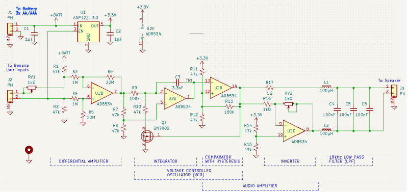
 The circuit is based on a single AD8534 quad op amp chip. The first stage measures the voltage across the circuit under test in response to small current and amplifies it. The resulting signal is fed into a voltage-controlled oscillator (VCO) made from one op amp connected as an integrator and another working as a comparator with hysteresis. Op amp number four amplifies the resulting square wave and drives a speaker. A low-pass filter makes the sound a bit more pleasing to the ears by removing the higher notes.
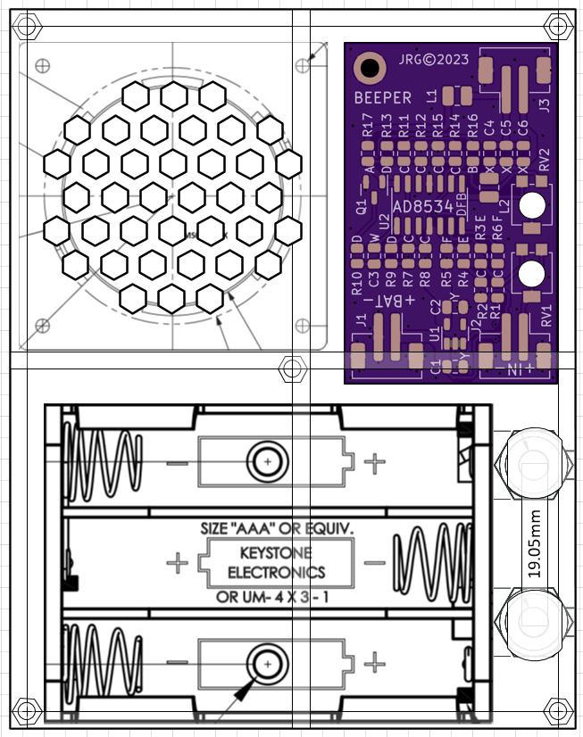
[John] paid particular attention to the PCB design to make it easy to assemble despite having a large number of SMD components on a small board. He even placed a parts list on the rear silkscreen, so anyone can assemble it even without the accompanying documents. The resulting board can be placed in a laser-cut acrylic case, turning it into a neat handheld instrument that will definitely find a place in any engineer’s toolbox. Measuring resistance through sound is not as accurate as using a full four-wire setup with an ohmmeter, but will be much faster and easier if you just want to find that annoying solder bridge hiding somewhere on your board.


Clever, I suppose. But can it locate a short resulting from a mid-layer filament resulting from a bit of dust in the original fabrication of the laminates? We were doing just that in the 1980s using a small DC current source and a device using op amps, called a current path indicator, or CPI. It was capable of measuring the voltages dropped across the short length of a single IC leg.
Just a heads up in case someone does not wish to make their own…”Production Devices” makes a very similar device to this one and is called the “Circuit probe Model 105”. The device is made in San Diego, CA and is priced at $26.90 USD (just googled the price). I have had mine for many years and it works great! It consumes very little power so much so that there is no on/off switch… and I have yet to change the battery.
This is probably much better and more modern, but concept not dissimilar to Beepo from EA back in the 1980s
https://archive.org/details/EA1989/EA%201989-01%20January/page/n69/mode/2up
I’ve made a few of those (with some modification) over the years.
Thar’s a clever design, thank you for the link.
Why does the author need an LDO? The opamps run happily up to 6V.
Because it disables the opamps until you connect the input to a low resistance.
The LDO is a late addition to the design, the disable function was originally a NFET with a very low VGSth. But the LDO solves the issue of linearizing the output amplitude regardless of battery voltage. I was trying to tweak this with back to back diodes but that ended up being clumsy. This, the LDO was added, not when volume is set to an appropriate level it stays that way until the batteries are dead.
This reminds me of the IC checker we used in the 80s to check for burned 74series ICs on computer boards: Just amplify the noise of the substrate diode of the IC. You can clearly hear the difference between good and burned IC without even having to know its function. It worked for the 4000 series too, but not as well as on bipolar ones.
I was shown this by a technician at the first place I worked using just a D-cell and an old school dc buzzer.
I built a four wire ohmmeter using a previous HAD contributor’s design and it works great.
Reminds me of the Polar Toneohm we use at work for checking for for shorts. Its like a mains plugged beeper tester for us, but it could be used to find the accurate location of shots, but we haven’t got around to learn how to do that 😁
I’ve been using a DIY thingy that does exactly this since the 80s. It uses a 555 and I call it the “Ohm Beeper”
It works exactly as the above linked “Circuit probe Model 105” but it omits that it can also test inductors and batteries. Those increase the tone depending on inductance or voltage.
My “reference tone” is 3300Hz, as this is the most sensitive frequency for most humans, and leaves plenty room for increased frequencies.
Xor the output with a 3.3khz signal to get the beat frequency and crazy sensitivity.
Can you share circuit schematic?
Sure, schematic is on Hackaday.Io