Almost every meter you find today will have a continuity tester. Connect the probes and it will beep if there is a short and won’t if there isn’t. But where is the short? That’s another problem when trying to measure a component that is connected to many other components. [Learn Electronics Repair] wanted to have a tool to find shorts on a board and wanted to build a tester that uses 4-wire resistance measurement to isolate the device under test without having to do surgery on the circuit. His $1 build appears in the video below.
The first part of the video talks about the theory behind resistance measurement with two and four wires. Let shows several diagrams, but he mentions that at one point he shows an incorrect schematic (at 12:03) instead of the early correct one (at 10:35) and mentions it, but if you are skimming the video, you might get confused.
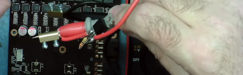
An old video card with an introduced capacitor short makes a good demo. The meter is able to tell where the short circuit is. The probes won’t win a beauty contest, but it looks workable. The measurement is actually the voltage drop induced by a constant current source, so it isn’t handy to read the actual resistance, but it will show you where a branch is shorted. You could actually do this essentially for free if you have a constant current bench supply and some extra wires.
We’ve covered 4-wire measurements before, with a focus on how they can zero out lead resistance, but the same idea applies. If you prefer your explanations in a video, we saw one recently.


Great concept but a few items to note. His drawn schematic takes the output of the regulator to the device under test but the actual build connects to the regulator’s Adjust pin (which is the correct one). Second point is that he is measuring the resistance from one probe tip through the device under test and through the second probe tip. But the contacts between the needle point tips and the device under test have their own resistance which may be higher than the short itself. Thus the use of four probes in the real milliohmmeter. But at least only having to handle two probes is much easier!
Ugh. 19 minutes 44 seconds PLUS uncountable useless YouTube ads to explain something that needs a couple-few written paragraphs and a simple drawing. Thank goodness Hackaday’s synopsis was succinct and informative enough to allow me to skip the video all together :-)
Yeah, right? TLDR: batteries + LM317 w/ resistor connected across out & adjust makes const. current supply.
Run ~50 mA through the DUT using this, read voltage drop off multimeter.
You could make this accurate by calibrating the current supply, but then you’d have math. You could make the math easy by picking round numbers for milliamps.
But then there _are_ clever bits here like using terminal blocks to screw the wires onto your probe tips, etc.
Youtube ads? No ublock for your firefox?
Oh yeah, I have 100% control over FFox. I usually allow (within limits) ads, after all the content creators deserve something as a reward for their efforts. But YouTube (Google actually) is getting so greedy these days I’m on the verge of locking them out all together. I do not use uBlock, I prefer to use the (now deprecated) uMatrix, plus some other layers, that gives me more control.
Where do you live? Even here in Argentina where everything is 200x I happily pay for the premium YouTube service (family plan) and enjoy not having any interrupting ads through the video, also, it would be awesome if you can post a video with couple-few written paragraphs and a simple drawing, IMHO you can only criticize if you made something better, oh wait, you didn’t. I remain silent coz I don’t have videos, so yes I’m a knowledge leech, but at least I don’t complain. Thanks for being polite, tho.
I understand and respect your position Ernesto. But I’m in a different place. I try to reward the content producers on YouTube by allowing some ads, but I will never directly pay YouTube (Google actually) for anything! Google has no respect for freedom of speech. Therefore I have no respect for Google at all.
Better use this method only on tube, relay and discrete BJT stuff, it might degrade or kill the protection circuits in many ICs and RF MOSFETs.
Not sure how at 50ma and 4.5v, or less, you pick your voltage input. Realistically, 2x alkaline or an 18650, so 3-4v should be fine.
Also, you are testing into a dead short. You’ve already determined a short, so chances of damage are minimal.
I’d love to see this completely integrated with battery in the handled XD
I had to order a 10-pack of lm317 to try this (already cleared a shorted cap on a Synology and a GeForce this year, but one was getting warm, and one was trial+error)
Would the 100ma mini lm317 be able to handle this? Because those are very cheap and smaller to integrate in a probe handle.
Consider this scenario: you have a short between ground and power, and one end of your probe is connected to ground. While testing, you accidentially hit an IC pin with a high impedance to the power rails. Now the current flows through the protection diode to the VCC pin and from there to the dead short. The protection diodes in the CD4000B series are spec’d for 10mA max, 74HC can take 20mA and most integrated stuff also lies within that range. 50 or even 100mA will lead to local overheating on the chip with nasty side effects.
I prefer to use a old school Octopus on a old Analog scope and some times a voltage injector to find shorts and opens.
I use a car battery. It clears most shorts, and the rest start to smoke so ypou know where they are.
Love it! If its blocked, turn up the pressure.
Whoops, there goes all my 5V components.
I use a current limited power supply and an IR thermometer. Works great. Been doing it for like 35 years.
Another way that an old (at that time) tech showed me is to use two probes connected to a D-Cell battery and measure the voltage across the battery. The lower the voltage, the closer you are to the short…
A kindred spirit! Good man. A cold pint for you sir!
How about a $0 option?
A bench power supply with current limit set to 50/100mA?
Sounds great! Where do I get the $0 bench power supply?
Your school lab, nearby hackers-pace, neighbor. Last one, didn’t has to even know, when morals are particularly low.
This is not as “common sense” as it should be.
Working for Motorola on boards with 50 decoupling caps…1 in a 1000 would be shorted from manufacture
Was instructed by the production engineers to use a sharp knife and split the supply bus in half. 5 or 6 trace cuts later I would hand the board to the rework girl to replace the cap and fix all my cuts.
Conceivably this technique would reduce diagnosis and rework time dramatically and leave a board that still looked new.
Having used a ToneOhm, which is silent until a short is probed, and the frequency increases as the resistance decreases, I know how easy they make finding a circuit short. I used one back in the days when most boards were less than 4 sided, but the sound feedback allows you to concentrate on where you’re putting the probes.
https://www.polarinstruments.com/products/toneohm/toneohm_950.html
The basic concept of a toneohm should be simple to make with a couple of 555’s and an opamp, but I’m waiting for a hacker to make one, and for them to appear on EBAY for under $10.
That sort of thing was in Radio Electronics or such towards the end.
Just use a hot air tool, your meter will go wazzo when directly over the short. (freeze spray works as well)