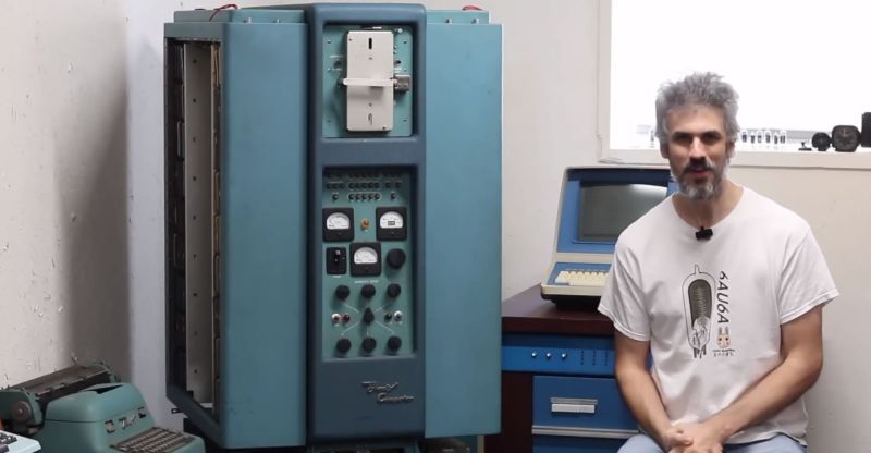
When it’s the 1950s and you are tasked to design a computer system that features not only CPU registers but also a certain amount of RAM, you do not have a lot of options. At this point in time, discrete logic was the rule, and magnetic core memory still fairly new and rather expensive. This is where the rotating drum comes in, which is somewhat like a cross between an old-style cylinder record and a hard drive. In a recent [Usagi Electric] video, a 1950s Bendix G15 system is demonstrated, which features such a rotating drum device, alongside both tube-based circuits and newfangled diode-based circuitry.
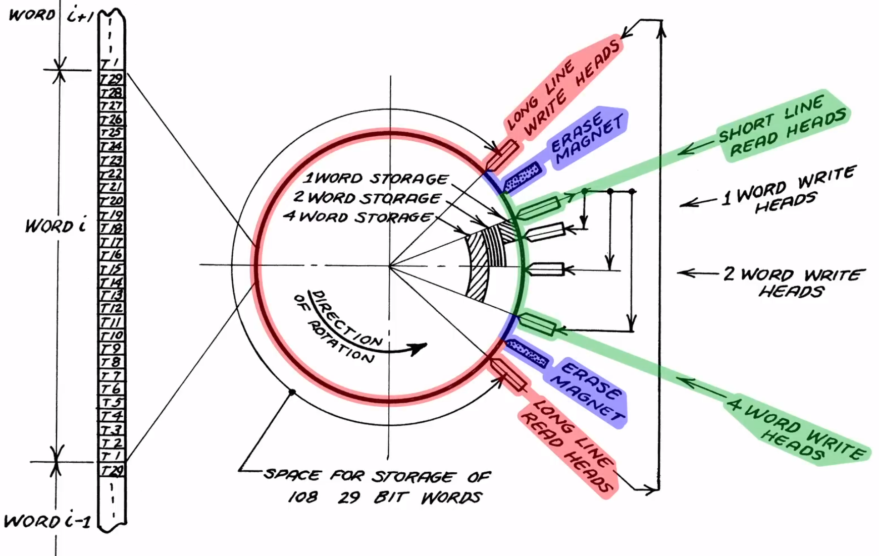
This particular unit was borrowed from the System Source museum, with the intent to restore it to a working condition. Part of this process involved figuring out the circuitry, which was made easy by the circuit schematic drawings that came with the original machine. According to the official brochure by the manufacturer, the ‘short lines’ that are intended for the CPU registers, the access time was less than 1 millisecond, which is pretty darn fast considering the era and the discrete CPU’s clock speed.
For the drum itself, however, popping the cover off the unit showed that it had suffered some damage that had resulted in the multiple heads contacting the surface. Despite this disappointment, it’s not the end of the restoration, however. The museum has one more Bendix G15 standing around, with a rotating drum unit that looks to be in mint condition. The damaged magnetic coating on the other rotating drum may conceivably be resurfaced, which if successful could provide new hope to a lot of retro systems out there that also use magnetic media, whether in drum or disk format.


No discussion of drum memory is complete without a link to the “Story of Mel”. (The computer he worked on was even mentioned in the linked video). It gives some insight into how drum memory computers worked, and could be programmed.
http://www.catb.org/jargon/html/story-of-mel.html
Thank you for that, Ive never seen it before. Interesting read!.
+1 Thanks!
I have two rotary drum units I haven’t tried playing with yet. This is great.
Very cool. Do you know where they came out of? I have wondered about where one could find a relatively easy-to-assemble aluminum drum with a precisely-centered shaft (I’m not a machinist but I suspect that an NC milling machine may be the only solution) to coat with iron oxide to try building a drum.
p.s. Another solution for starting from scratch would be to hack an old disk drive. Autonetics (anybody else?) used disks like drums.
Burroughs had head-per-track drives, as did DEC (DF32). I’m sure plenty of others did, as well.
On the Burroughs 3500 I used to program for, the head-per-track drive was a platter (oriented vertically!). However, the computer at CIT (now Monash University) had an ICL 1904A with the OS (George III) living on a mag drum.
Yes, if one could find a spare Burroughs HPT disk or a spare DF32 or similar that was not being used in a restored machine, I suppose it could be used *non-destructively* as a drum. I’d hate to damage it though!!
A good manual lathe can hold 40 millionths of an inch across its working distance. You could also add in a voice coil that keeps the head floating off the surface with a feedback mechanism and null out slight out of round issues.
Just one simple design change and you have a washing machine. Or was it the other way round?
The inertial engagement mechanism on older starter motors was also a “Bendix”
“starter” as in internal combustion engine starter. The Bendix being a funny little lead screw type thing that sort of acted like a diode for torque, so the electric series motor could crank the engine but not vice versa.
Bendix is just a company/brand. Oh and also a genericized trademark.
Yes, I think we all know that. But one with a rather diverse range of products, historically. There isn’t a lot of crossover between a fast-thread engagement screw and a vacuum tube computer.
https://en.wikipedia.org/wiki/Bendix_Corporation
Though apparently they didn’t make the washing machines, just licensed their name.
The Burroughs 205 had a drum memory that stored something like 8000 digits. Yes, digits. There would be a set of four parallel tracks such that you could read 4 bits at once for one digit (and a few extra ‘control codes’), and that was replicated 8 times along the drum axis. Registers held 10 or 11 digits, something like that. Anyway, to “read memory” must have involved keeping a counter sync’d to the drum angle, and shift registering the desired bits as they passed by. Amusing to think about
Fwiw, the B205 was the blinkenlighter that played the Bat Computer for Adam West’s famous show, and also featured in the Lost in Space of the same era.
I absolutely love this video series, it hits the exact soft-spot for me on vintage systems. The re-surfacing of the drum will be SO cool, I’ve been waiting for someone to try it for YEARS.
After a quick introduction to the world of data processing on punched card accounting machines (PCAM)we started to learn programming on an IBM 650. With a bi-quinary internal numbering system, 10 position words and a 2000 word rotating drum it was state of the art for 1960. Drum memories will not be missed.
I’ve been working on the G15 as something to implement in an FPGA. It wouldn’t be too darn hard to make a substitute for the drum with an FPGA and appropriate analog interface circuits to drop into the real beast. The drum is completely central to everything in the G15. Without the drum, the lights don’t even blink. If the rest of the machine wakes up, then the dummy drum could be replaced by the real thing. As I’ve been trying to get a gate level simulation of the G15 to work, I can say that these machines are quite inscrutable. Very hard to debug. The germanium diodes in the G15, for example have a very high soft failure rate. I am in awe of the engineers who got these to work with the primitive tools of the day.
Yes, you could emulate a drum with a shift register for each track, and short shift registers for the short tracks, all clocked together. Look at the Kenbak 1 design. The only question is, these days, how to find long enough shift registers. (Sorry, I haven’t looked lately to see what is available.) An alternate would be a RAM with a bit in the word for each track and the address from a counter. (Read the word into a register, modify a bit in the register if needed, and rewrite the word if needed, before bumping the counter. You could use a smaller RAM with fewer bits in a word and a counter with fewer bits for the short tracks.
An FPGA implementation would be able to put all the drum into one chip. A big advantage of this approach is that the pseudo-drum could be run one clock at a time. This would allow efficient debug of the logic in the computer. Finding the ancient connectors to make a drop in replacement might be the biggest challenge.
Does anyone have any pointers to how one might make their own? It seems like you can use Iron (III) Oxide powder, mix it with some binding agent (glue?) and apply it to a non-ferrous drum (like aluminum). But I am not a “materials” person and don’t understand the details of what I just said :)
Yes. I have thought about using the commercially-available paint with iron already in it that is sold to make walls to which magnets will stick. (There was an episode of ‘the secret life of machines’ about the audio tape recorder where they did something like that.) I don’t know smooth it is, perhaps it would be smoothed with polishing compound after it is mounted and spinning. (I just worry about centering it accurately to get the heads close and avoid head crashes!) One place to look for inspiration is pictures of some of the early drums (the one at Manchester for their Mark 1 was initially called a wheel) and early papers telling how the researches way back then built theirs. This picture makes it look wonderfully simple:
https://collection.sciencemuseumgroup.org.uk/objects/co62443/experimental-magnetic-drum-store-memory-devices
Search this page for ‘drum’:
https://en.wikipedia.org/wiki/Manchester_Mark_1
See also the references here:
https://en.wikipedia.org/wiki/Drum_memory#History
This strange(?) search engine for rhymes(!) find many hits:
https://www.rhymezone.com/r/rhyme.cgi?typeofrhyme=wke&loc=defwk&Word=magnetic_drum
Perhaps a local shop that does powder coating can help.
If we can find a sheet of floppy disk material we could wrap that around the drum but there would be a seam that the heads would have to clear.
Hmmm, if we can find large diameter bearings and a large enough shaft that isn’t too heavy, perhaps the shaft itself can be the drum.
Using a timing track (perhaps optical instead of magnetic??) for the computer clock would solve problems with speed variation, this was done on some machines in the old days IIRC.
Can anyone find a copy of this paper online? (The URL munging described in the redirect page does not seem to work.) See also: https://en.wiktionary.org/wiki/alligatoring
https://apps.dtic.mil/sti/citations/AD0658092
ccession Number: AD0658092
Title: A METHOD FOR COATING MADDIDA MAGNETIC MEMORY DRUMS,
Descriptive Note:
Corporate Author: JOHNS HOPKINS UNIV SILVER SPRING MD APPLIED PHYSICS LAB
Personal Author(s): Smith,C. Dixon Irving,I. B.
Report Date: 1953-04-01
Pagination or Media Count: 7.0
Abstract: A technique was developed for applying a smooth coating of a magnetic dispersion to an aluminum drum used as a magnetic memory for a maddida unit. The finished unit is free from flaws such as alligatoring and has a coating thick enough to give a 0.7 volt a.c. electrical output when the recording is made with a 300 turn winding recording head and a 50 ma. d.c. input current. Author
According to https://apps.dtic.mil/sti/citations/AD0658092
you can request the text via a FOIA request.
From: https://www.ams.org/mcom/1950-04-029/S0025-5718-50-99480-4/S0025-5718-50-99480-4.pdf
“The magnetizable medium on the drum surface is a smooth, sprayed-on coating of magnetic iron oxide, the same material which is used on magnetic sound recording tape. This surface is protected by a thin over~coating of a hard lacquer.”
Also see: http://gallery.lib.umn.edu/items/show/2368
A discussion of the coating material can be found in: https://patents.google.com/patent/EP0035633A1/en
An interesting memory, I worked using GE drum in 1966, and Multix used the drum at MIT for the GE-645 and the first VM designed, followed by UNIX, and Linux. Yes, I’m old, but we were the cutting edge then.
Analog C-130E flight simulators had a DFG (Digital Function Generator) that utilized a basket ball sized memory drum. The sim was built in early ‘60’s and required the DFG to handle the rapid changes of fuel flow & torque that analog circuits couldn’t handle. They retired the DFG around 75/76 and replaced it with a National Semiconductor IMP-16 mini computer, but left the DFG in place in its rack in case it was needed if the IMP failed (it never did).