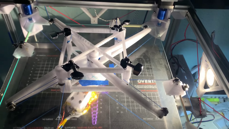
In the early days of FDM 3D printing, the RepRap project spawned all sorts of weird and and wonderful designs. In the video after the break [dizekat] gives us a throwback to those times with the Marionette 3D printer, completely forgoing linear rails in favor of strings.
The closest thing to a linear guide found on the Marionette is a pane of glass against which the top surface of the print head slides. A pair of stepper motors drive the printhead in the XY-plane, similar in concept to the Maslow CNC router, but in this case two more strings are required to keep the mechanism in tension. To correctly adjust the length of the string across the full range of motion, [dizekat] uses a complex articulating pulley mechanism that we haven’t seen before. The strings are also angled slightly downward from the spool to the print head, holding it in place against the glass.
The bed print bed is also suspended and constrained using string, with no rigid mechanical member attaching it to the frame of the printer. Six strings connected to the sides and bottom of the bed frame constrain it in 6-DOF, and pass through another pulley arrangement to three more strings and finally to a single stepper driven belt.
We can’t see any particular advantage to forgoing the linear rails, especially when the mechanisms have to be this complex, but it certainly make for an interesting engineering challenge. Whatever the reason, the end result is fascinating to watch move, and the print quality even looks decent.
One practical advantage to some cable-based 3d printers is on the large scale, where it can turn an entire room into usable print volume.


Bonkers, but brilliantly different. It seems excessively complex, but I can’t immediately see any way to simplify it while using the same string concept.
I can however think of one reason this idea might really have merit – as the print head is riding on a ‘flat’ surface that you can at least in theory easily reflatten – in effect you could print on a surface place using another surface plate for reference and avoid the problems of much more difficult to reshape and expensive to replace linear rail wearing, as almost all the important to print precision geometry here is in the string tension being held against that flat plane.
I personally disregard its complexity for now, To me the interesting thing is that the contraption has the potential to print more of its own parts now that linear rails are out of the picture. It would be fascinating to compare how much of it can be self-replicated, compared to the original RepRap. I think bootstraping hardware remains a worthy goal. Excepting obvious parts like electronics, power supply and extruder, it looks it may be possible to push the limits even further. For example, for those guitar string tensioners a 3D printable ratchet mechanism may be possible.
True, in terms of reducing remotely manufactured and not self-replicating components this could get you rather close – bit of braiding with the right filament or designing the system to use flat belts you could print and you could even replicate or at least use the same feedstock for the strings if you really wanted to.
Though personally I’d definitely stick with guitar tuners and other metalwork on show – so much more compact and reliable. As unless you are building this inside a fancy enclosure to use the more warp or layer adhesion issue prone but better engineering plastics or have the burn out oven to turn the suspended powdered metal/ceramic parts into better parts the footprint would have to grow hugely and the friction would skyrocket. The common 3d printing plastics are just not that good especially while under relatively high permanent tension.
For the tuners I have a plan to implement automatic tuning using a mechanism that applies equal force to 4 strings and has a clamp that clamps all 4 strings. You would move the toolhead and the linkage (“marionette”) to the center, lock them in place using centering jigs, undo the clamp, and then re-do the clamp, and that’ll be all.
Same for the Z axis, the pieces you can see on the sides of the printer that are not doing anything, are for assembly and adjustment: you remove the bed, move the print head out of the way of the cross, raise the cross up and lock it in place using 3 pins, lock the googly eyes pulley in place using another pin, then you tension all the cables to equal tension. Eventually that will be as simple as undoing and re-doing a bolt or two.
I’ll make a video some time about the alignment procedure, once i make the equal-tensioners.
Agreed, it’s totally bonkers. What an awesome hack!
I’m not convinced about the costs of surface plate refinishing and calibration versus linear rail replacement. It theory it’s easy to use the 3 plate method to ensure flatness, but practically speaking, proving flatness requires tools that most people don’t own, and measurement techniques and calculations that are non-trivial. On the other hand, even cheap linear rails are pretty darn good when mounted to a stiff flat surface, have a good lifespan when used and maintained correctly, and anyone can easily learn how to replace them. One potential advantage of this system is a reduction in metal. I’m not sure exactly where that is an advantage though, perhaps somewhere where 3D printing is needed in strong (electro)magnetic environments? Or where the mass of the printer is relevant (space perhaps?). In that regard, the string scales beautifully for larger printers in a way that rail does not, but that is offset by the mass of the plate which is determined by area…
The low angle of the strings here limit the upward pressure that the nozzle can place on the plate, and probably contributes to the chatter at higher speeds. That’s a non-trivial problem to solve. Increasing the angle (by making the print head taller) would help, but would likely exacerbate any non-linearities in the motion. Increasing the string tension would too, but would increase friction and wear throughout the system. I suspect that the strings will suffer from long-term creep, requiring them to be retensioned periodically. One of the low-stretch UHWMPE kite string variants is probably a good candidate to minimize that.
At a 3D printing trade show this summer, someone demonstrated an upside-down FDM printer where the model was hung from the bed, much like a resin printer. I wonder if that might be a useful technique here. The angle of the strings could be minimized to almost zero, and gravity would keep the print head on the plate. An air bearing calibrated for the mass of the print head could reduce friction to a minimum and would likely eradicate chatter. I’m thinking that the chatter probably occurs when the leading edge of the print head experiences some friction or stiction, and the trailing edge drops from the plate.
You really don’t need to prove flatness to any great extent for this, no professional level refinish would be required – the 3d print layer thicknesses are going to be probably more than one order of magnitude larger than the worst outcome you can possibly achieve when sensibly trying to flatten the plate, which in fairness i highly doubt you would ever have to do after construction as its upside down so hard grits won’t collect and get rubbed in to cause real wear (even less likely to be required if they do move to using an air bearing).
Plus you do have to consider thermal effects if you are getting that deep into the precision woods. – the plate would only ever be properly flat at the correct temperature even with masterful job and all the measuring tools to prove it is ‘flat’.
I love the idea of the glass plate and the head riding on it. The Z axis seems overly complicated, just imagine leveling this madness. Maybe some hybrid could be made with a more traditional Z axis motion.
Leveling is actually pretty straightforward. You can see the pieces on each side that are not doing anything, they’re for leveling. You install the bed cross holding it in place at 3 points using pins, then you lock the weird shaped pulley up front using another pin.
Then you tension and clamp under tension every rope. Once that is done, since the ropes are tied together they maintain level movement (unlike a linear rail, 6 ropes also constrain well against bed tilting). To prevent knots from tightening further under load, you tighten them with a lever then add a drop of superglue to each knot.
Seems like there would be some acceleration limits not present on a traditional FDM model but I could be wrong.
So far initial motion testing has yielded 1.5m/s @ 100m/s2 acceleration
I’ve been looking for a right angle hot end. Did you make your own or buy it somewhere? Any information about constructing or purchasing one would be greatly appreciated!
Made it myself, I need to make a whole video about it…
Basically first i made a short length of 2mm ID 3mm OD copper pipe into a nozzle by swaging one end shut and drilling it to 0.4mm .
Then I threaded the other end with m3 thread. I took a Volcano hotend, drilled it out to 2.5mm on the nozzle side, then to 3mm (shallowly), then screwed in the copper nozzle.
Tested for leaks, when screwing in to the end no leaks (copper forms a seal). Bent the now plastic-filled nozzle the required angle using a little 3D printed tool to make sure to maintain a large enough bend radius.
To point the nozzle in the correct direction you rotate the heatbreak (which is held inside the heatsink with 2 grub screws). One drawback of this construction though is huge die swell; I may make another one using a short commercial nozzle with copper pipe as the bent extender.
Check out the Positron. It has a right-angled hot end:
https://m.youtube.com/watch?v=YV39cYB-tlU
Thanks, I checked it out but I didn’t see any offerings of design files or purchase options for a head. LOBO CNC UDIO 3D printer with a right angle head was mentioned in the video with a link to it (couldn’t find the link though)
There are design files in the repository: https://github.com/KRALYN/PositronV3/tree/main/CAD%20%20files/Engineering%20Drawings – look for the two Hotend PDFs.
Cool, so the next disney movie will be ’Pinoccio A.D. 2030’ is a printed not carved pinoccio. :-D
I hope japanese (manga) and south korean (manhwa) inspired with a lot of build in self defence systems :-)
I thought I had seen it all with 3D printers, very interesting approach.
I proposed a couple of posts back that Hackaday should give awards for beautifully simple design.
This would not win that prize.
And, it displays no advantages for its complexity, save that of being overly complex.
Kudos for winning a Rube Goldberg award.
https://www.historydefined.net/rube-goldberg/
You are going to want to swap out that string for something stronger. Braided steel seems like a better option.
Yeah, and the guitar tuning pegs are already there..
It’s not immediately clear what that string is. Ultra High Molecular Weight Polyethylene is probably the best choice, a kite string being a likely option. It’s about 20% stronger than steel cable rope of the same diameter, whilst being ridiculously light.
Any chance they could use a magnet to hold the print head to the glass from the back side? Could make the string tension less important possibly? Then you would need some kind of bearings on the top and bottom, teflon sliders at the very least. Although it seems like they sat some of the pulley mechanism up top.
Another option is flipping this upside down and lifting the model away from the print head. So crazy to see the history until we got to $99 Ender 3 at MicroCenter.
In one part of the video, the creator talks about adding in a vacuum bearing to pull the printhead to the glass.
Had pretty much the same idea when seeing the glass plate.
Strong magnet in the top of the printer head assembly and maybe steel ball bearing on the top of the glass plate – and then move the ball bearing instead of the head or something?…
Or an array of electromagnets on top of the glass plate moving the head without traditional motors?
Would waste a lot of energy but maybe there are some special use cases for that?
I seem to remember Stratasys had a magnetic plate arrangement, I think it was called magnadrive or some such name.
looks like this as a printer
https://www.youtube.com/watch?v=W7nGL-_5SDw
The concept of a 3dprinter that can print itself is getting closer. I wonder if it can print it’s own ropes.
For anyone who missed this concept the first time…
If you want unlimited build space here ya go
https://reprap.org/wiki/Hangprinter