Building a crystal clock source for a CPU used to be a bit of an effort but these days, there’s nothing to it. Even if your CPU or other device needs an external clock, you just slap in an inverter, a crystal, and two capacitors together, and you are done, right? Maybe not. [Dave Collins] got interested in the common circuit and pulled out his scope and an array of different kinds of inverters. He looked at inverters and NAND gates and a few common circuit configurations.
This is one of those things you just assume is of little importance, but it turns out your choice of circuit architecture and active device can have a big impact on the output. But who has time to do all the testing? Thanks to [Dave] you don’t have to.
Honestly, we are as likely to just buy a “can” oscillator if we need something like that these days. But still, it is interesting to see what kind of differences there are between using different inverting elements.
Crystal oscillators are relatively ancient tech, but they still beat everything until you get into exotic and expensive things. If you want to look even deeper into what goes into these, [Ken] can help.


Kinda reminds me of the GDR PolyPlay arcade machine, on one, the screen started drifting (H-freq) and the machine started crashing when warm. So I checked the main oscillator and it wasn’t a quartz, it was a ceramic resonator (at 10MHz nontheless). And even cold it would drift significantly. They used the 7404 circuit and the 7404 got very toasty. We have two of these machines so I compared to the other one. There, the 7404 only got warm and didn’t drift.
So I replaced the 7404 and found the frequency to be waaay off (like 9MHz). Since I had it socketed, I also tried different types of 7404 (7404, LS04, HC04) and the marginally faulty original chip was the only one who would get close to the target frequency. The HC04 also got the frequency right, but introduced so much jitter that the picture looked abysmal with every other scanline at a different position.
I noticed fingering the circuit got the frequency right, the monitor to sync up and the picture to look OK, but changing resistors around or throwing extra ones at the circuit didn’t make it work reliably.
I ended up cheating and replaced the entire oscillator circuit with a 10MHz quartz and an LS04.
Interestingly enough there’s loads of early entertainment devices with 8-16 MHz ceramics the zx81 has one and it uses some internal circuit side the ULA to build the clock for the z80 off that. There’s a modern replacement to the ULA which uses a SMD can to generate the clock and basically abandons the ceramic.
The 74HCU04 trick for making a simple amplifier is a nice one, but awfully current hungry. Like 20mA, for a small input signal, even with no load on the output. Usually you only dare use one or two channels of a hex chip this way, else you’ll be drawing more current than the power pin of the chip can withstand. I’d be interested if anyone knows of tricks to use this without having such high current draw.
So I got interested, and looked! In this configuration the circuit draws about 10uA – thats high for 1 ic. It can ground out 50uA and withstand 20uA across the power pin, that’s still running the chip flat out at 50% all the time. Definitely way more than a can oscillator. As far as making it work with less current – I think the issue is the first inverter is literally hanging at the switchable region, because of this it’s constantly drawing current. There are other circuits that may do this better – operational amplifiers come to mind, but again as these circuits run wide open it’s always going to generate a ton of current. Ken Sheriff has a wonderful write up on the inner working of a can oscillator thats linked above, one of the big reasons to use a discreet cmos oscillator is that they are significantly less power hungry.
Gads… I said uA measurement is in mA apologies 😅
Since we’re on the topic, what inverter is better for a beginner looking to build their first
1. 24VDC to 240VDC using flyback transformer, H bridge for actual AC generation
2. 24VDC to 240VAC using 60Hz transformer (probably centre tapped)
(yes I read the article but I still chose to post about the wrong kind of inverter)
2nd one. First one wouldn’t work. The flyback isn’t designed to give that sort of voltage, high chance you will get kV outputs instead. Also, your power transfer ratio will be absolutely horrible.
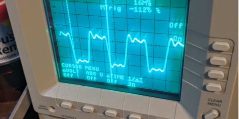
The scope images show a 16 MHz square wave. There’s a photo of a solderless breadboard with a crystal with markings that might imply 16 MHz. Although he’s done an excellent job of keeping component leads short, there’s still a lot of ringing at 48 MHz. He might have been able to clean things up a bit with a 0.1 uF capacitor directly between power and ground pins on the IC. In any case, there’s a lot of stray capacitance and other problems with solderless breadboards that make 16 MHz tricky for an oscillator.
The final choice of the unbuffered 74HCU04 makes a lot of sense: lower gain, particularly lower gain at high frequencies to prevent the generation of harmonics.
I should have said, I did point to point soldering on a plated through holes PCB for the majority of the tests. The breadboard was just the NAND gate. I did actually have the tiny bypass of 100nF in the breadboard as well.
That confirms that standard logic gates do not make very good crystal oscillators.
I do not agree at all with the “assume is of little importance”. In these modern times you can’t just slap on any crystal onto your microcontroller and expect it to work. For example in AN2867 st has a 59 page document about considerations for using a crystal for their uC’s. It is worth having a look at for anyone making the jump from buying ready made PCB’s to designing their own PCB.
https://www.st.com/resource/en/application_note/cd00221665-oscillator-design-guide-for-stm8af-al-s-stm32-mcus-and-mpus-stmicroelectronics.pdf