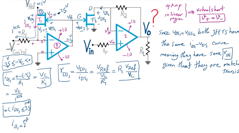
Normally, if you want to control the gain of an amplifier, you’ll use a variable resistor. You know, like a volume control. But what if you want to control the amplifier’s gain with a voltage? [Engineering Prof] explains a circuit that can do this using a pair of op amps and a pair of matched JFETs.
The analysis is simple because you assume the op amps are not in saturation, so you can assume that the op amp will do what it needs to do to make the input terminals equal. The left-hand op amp has one input grounded, so the output will drive the first FET to ensure the negative terminal is also 0V. It is easy to see that the current through R1 must then be the current through the FET, which is going to be the control voltage (which is negative) divided by R1.
The gate voltage on the first JFET’s gate is the same as the gate voltage on the second JFET. Since they are matched, you can assume the current through that transistor will be the same as the first transistor. If you make sure the control voltage stays in the linear region of the FET, the device works somewhat like a variable resistor.
Confusing? Watch the video below, and it will all be clear. We might suggest you simulate it if you really want to understand it. If you don’t like your simulator in a browser, there are always choices.


Or if you’re like my old receiver, you just add a motor and a little belt to a potentiometer for the remote control
You have to admit, the results were pretty satisfying though! The little belt and motor added just enough resistance to make the phrase “Crank it up!”, make sense! And seeing the physical volume knob rotate as you press the buttons on the ir remote is way cooler than some led bar graph, or a number incrementing.
Many pro recording consoles with fader automation were exactly that- motor + belt or string arrangements moving linear faders. The faders had two tracks: the audio fader track, and a separate linear track that provided the position feedback.
Nice article, but yeah I’d probably reach for a transconductance or VCA ic if I wanted simple voltage control of audio level.
* Motorized Slide Potentiometer – 10KΩ Linear with 5V DC Motor Product ID: 5466 $24.95
https://www.adafruit.com/product/5466
* Taking a look at a motorized linear potentiometer
https://www.youtube.com/watch?v=r12wG7ebvnY
https://www.youtube.com/watch?v=r12wG7ebvnY
I cringe when I see math but there was a 8 pin chip with 2 VCA’s recall, easy. I couldn’t remember the number. On looking up dual VCA I see it is now available once again AS3360 pin for pin CEM3360. Yes! Perfect stereo volume control.
You guys ever heard of a vactrol?
I haven’t.
A variable resistor (Light dependent resistor LDR) controlled by an incandescent lamp. I have one in a junk box somewhere. Little metal can like a radio crystal would be mounted in.
Dual matched JFETs are completely impractical and unobtainium unless sourced from a boutique supplier.
I should know, I found some from Linear Systems and bought them, a small fortune.
Practical gain control for decades was done with CdS photocell and lamp (neon, now LED) and you can buy VTL5 etc. from our favorite Asian supplier. If you’re an applied hacker verses theoretical.
Here’s a problem with Professors: when they are teaching courses on circuit design, they are teaching future chip designers. He says at least twice in the video, “matched meaning they are at the same temperature on the same substrate.” This does not mean, just go out and order some matched JFETs. It means, this works if you’re designing an analog chip using a CMOS process.
Oops, not CMOS!
TI have released a very low noise matched pair. JFE2140
Dual matched FETs are cheaply available in the 4007UBE. They’re very accurately matched as they’re on the same silicon die, and etched together. I have designed several commercial products that have made good use of the identical nature of those uncommitted FETs in that cheap CMOS part!
I use an led shining on a ldr. We use that system on the amplifier packs in the ATC SCM active speakers to prevent amplifier clipping. It works without introducing distortion.
This is how Tektronix made variable-bandwidth filters for some of their spectrum analyzers. They used crystal filters that needed resistors in series with capacitors to ground, between crystals, to vary the Q of the crystals. And since this all had to be isolated, they used a device that had an LED and a cadmium-sulfide photoresistor inside a TO-5 can. Worked fine, but it took literally seconds for the bandwidth to settle.
Mouser carries That Corporation VCAs and RMSs.
If you want low distortion, this is the way to go. Not cheap ($6), but quality.
The THAT VCAs are wonderful devices, and I have made good use of them in my current broadcast audio processor designs. You’re right about the prices, but quality often costs a lot!
Synth DIY folks have found the same. Great amp chips.