It probably comes as little surprise that our planet is practically buzzing with radio waves. Most of it is of our own making, with cell phones, microwaves, WiFi, and broadcasts up and down the spectrum whizzing around all the time. But our transmissions aren’t the only RF show in town, as the Earth itself is more than capable of generating radio signals of its own, signals which you can explore with a simple sferics receiver like this one.
If you’ve never heard of sferics and other natural radio phenomena, we have a primer to get you started. Briefly, sferics, short for “atmospherics,” are RF signals in the VLF range generated by the millions of lightning discharges that strike the Earth daily. Tuning into them is a pretty simple proposition, as [DX Explorer]’s receiver demonstrates. His circuit, which is based on a design by [K8TND], is just a single JFET surrounded by a few caps and resistors, plus a simple trap to filter out the strong AM broadcast signals in his area. The output of the RF amplifier goes directly into an audio amp, which could be anything you have handy — but you risk breaking [Elliot]’s heart if you don’t use his beloved LM386.
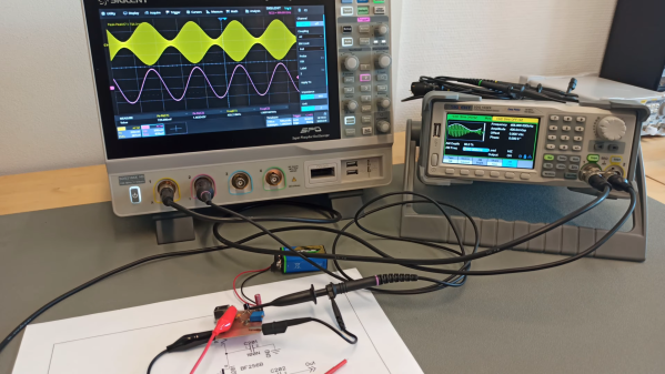
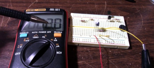
This is definitely a “nothing fancy” build, with the RF section built ugly style on a scrap of PCB and a simple telescopic whip used for an antenna. Tuning into the Earth’s radio signals does take some care, though. Getting far away from power lines is important, to limit AC interference. [DX Explorer] also found how he held the receiver was important; unless he was touching the ground plane of the receiver, the receiver started self-oscillating. But the pips, crackles, and pings came in loud and clear on his rig; check out the video below for the VLF action.
Continue reading “Homebrew Sferics Receiver Lets You Tune Into Earth Music”