We often use linear regulators in our designs. They are cheap and simple – you put the regulator chip itself on the board, add two capacitors, and get a voltage. Linear regulators are imperfect, of course – they can’t help but waste the voltage difference as heat, for a start, which straight up excludes them for high-current purposes, or significant voltage difference conversions, unless you have a hefty heatsink handy. They also can’t boost voltage, which means you can only go from high to low – a bit of a disappointment.
Of course, we haven’t been just throwing our hands up in the air if a linear regulator doesn’t fit our purpose. Switching regulators have none of these disadvantages, which is why your mobile phone alone has a few dozen of these. They are way more efficient and hi-tec, able to convert one voltage into another while losing hardly any power into heat. All that you need to do is switch an inductor at a somewhat high frequency!
 However, for some, switching regulators might look a bit intimidating. They tend to have higher standards for board layout compared to linear regulators, and, they do need an inductor – sometimes, a few more components too. Inductors alone are somewhat intimidating components, with a fair few more parameters than we’d expect, and you might get confused when looking into adding a switching regulator to your circuit.
No more! In this article, I shall give you the switching regulator basics, remove any fog of war that might be clouding your vision, and show you just how easily you can get a good few amps at your favourite voltage whenever you need it.
Finding Your Faves
There’s myriads of switching regulators you can use for many different purposes! For instance, buck regulators can only decrease voltage, boost regulators can only increase it, while buck-boost can do both, allowing you to get, say, 12V from a LiIon pack that varies from 10V to 14.4V. There’s two ways you can find yourself some switching regulator friends – either getting part numbers from somebody else’s circuits, or by going through Digikey/Mouser/etc and seeing their offerings.
There are switching regulators for most purposes you could think of. Want to convert 12V into a few amps of 5V or 3.3V? You have a ton options here! Want to make 5V or 3.3V out of LiIon voltage? There’s a good number of regulators for this exact purpose! An extremely low-power regulator that produces 3.3V for your ESP8266 from two AA batteries? You got it! And, the simplest option possible is borrowing a circuit from an existing reasonably-open or just publicly visible design.
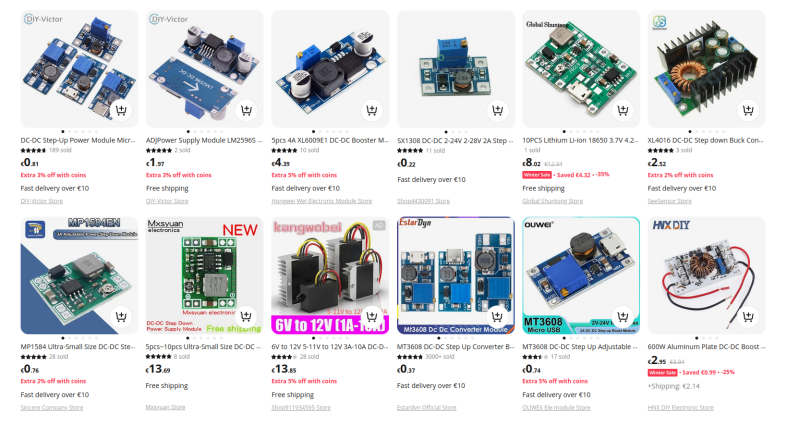
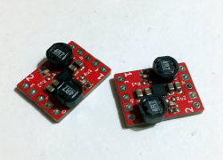
For instance, there’s a ton of different “DC-DC” boards you can quickly find online – on Aliexpress alone, there’s dozens of popular designs, and a good amount of more obscure ones too. Simply enter “step-down DC-DC 5V”, any configuration/voltage you want, find a few listings which are actually accurate, and see which chip they’re using. Can you find the datasheet? Can you buy it easily? Some listings lie about current values, so, can the chip actually produce what you need? If so, you are set!
Of course, for many purposes, you can reuse those modules and not worry about even looking for your own designs. However, most often, making your own switching regulator circuit will pay off – both in price, but also in your circuit’s stability! For instance, an open secret is that these modules tend to have badly suited inductors, either cheapest parts possible or just miscalculated values. So often, you only have to replace the inductor to see the output current skyrocket, and see the heat output decrease overall, too!
Often, the switching regulator ICs used on these modules, are also the cheapest chips possible, and there’s better ICs available for hardly more money. So, go visit the switching regulator parts picker of your favourite parts website – Digikey/LCSC/Mouser or whatever else. Put in your desired input and output voltage ranges, maximum current with some leeway, check “In stock”, sort by price, and see just how far you can get under $1!
My personal faves recently are a good few. PAM2306 is a dual-rail 3.3V/1A buck regulator able to do 100% duty cycle, which helps a ton when powering stuff from a LiIon or LiFePO4 battery. AP63200 can do 5V or 3.3V at 2A from as high as 30V, which is rad for my USB-PD shenanigans! And, on the Eastern front, SY8089 is a good pick for general low-voltage rails. Got some regulators you’d recommend to others? Share them with us in the comment section!
Found a chip you like? Cheers! The overwhelming majority of them need an inductor. Let’s waste no time and learn about those.
Meet The Inductor
Inductors are coils of wire made in a certain way, able to store a good amount of electromagnetic energy under the right circumstances. They also resist changes in current by producing an opposite voltage. Someone more inductor-savvy than me could tell you a ton about how inductors are seriously cool, and they absolutely are very cool! And, for switching regulator use, you don’t need to know a lot about inductors to use them. What you do need to know is that a switching regulator chip makes use of these characteristics to convert one voltage into another, and there’s only three parameters you really need to keep track of.
First one is inductance, usually, in uH (microHenry) range. Your switching regulator’s datasheet will either straight up tell you which inductance value is a good fit, maybe in the example schematic or in the “recommended parameters” section, or, it will give you a formula to calculate the inductance you need. If it doesn’t give you either of these two, look into values that other people use with this chip, or pick a different chip – more often than not, there’s other switching regulator chips you can use just as easily and that actually have good datasheets.
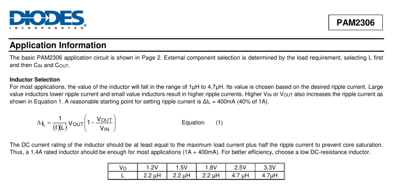
Another value is DC current. Again, a lot of datasheets will straight up hold your hand while walking you through inductor selection, and the PAM2306 datasheet I show above, tells you that DC current is your maximum current plus ripple current, and you can assume ripple current to be 40% of maximum current you want. If you want to know for sure, the datasheet gives a formula to calculate a more precise value, but generally, the datasheets I’ve checked, do tell you to add 40-50%. So, if you pick inductor DC current to be 1.5 times larger than the max current you want, you likely won’t go wrong.
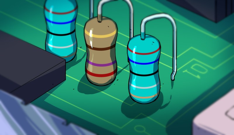
You might also see a specific parameter, DC resistance. The lower, the better, of course – less current wasted as heat. It’s not just waste, either – the kind of inductors used in switching regulator applications have their characteristics rapidly worsen when they heat up. Also, some inductors aren’t at their best when being used for switching regulator purposes, even if they look the part. Here’s an example of such an inductor. This is a power rail filtering inductor, and if that’s what you stumbled upon, there’s likely a power inductor (the kind you use for switching purposes) available with better specs that’s a much better fit for your application – not that it’s 100% unusable, but you will benefit from looking further.
Let’s sum up just how simple it is to find an inductor. Three parameters – inductance, DC current, and DC resistance. Inductance is in the datasheet, DC current is your desired max current times 1.5 give or take, and third is as low as you can go for your money. Plus, check that the inductor is suited for switching regulator applications. Looking to learn more? Here’s some appnotes – here’s a Wurth appnote on inductor intricacies, and a TI appnote on switching regulator basics.
Go to your favourite component picker website – Digikey, Mouser, LCSC or anything else, – put the inductance and DC current parameters into the inductor part picker, find the best DC resistance for your money, and you’re set. Hell, you can even find inductors on Aliexpress! They don’t tend to list DC current/resistance parameters, and datasheets are few and far between, but if you need something simple and cheap, it’s on the table.
 Found an inductor? Get the datasheet, see if KiCad already has a fitting footprint, if not, just take an existing footprint and adjust it, and that’s it. We got the regulator chip, we got the inductor picked, now it’s time to design a board!
In Case You Get Lost
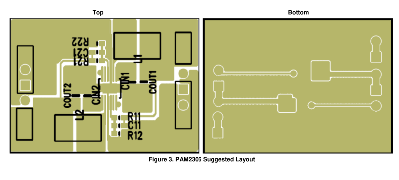
If your regulator’s datasheet is good, you are already set. The best datasheets provide an example layout, show you which resistors to use, mention any extra components, capacitor requirements, and teach you everything else you could want to know.
Not all of the datasheets contain everything you’d want to know, however. It’s a bummer, but, it doesn’t mean you can’t get it done! There are only a few aspects to mind – board layout, feedback resistors, and any extra components you might need. Next time, let’s go through these, and I’ll show you some switching regulator tips&tricks too!


What no love for the Recom add in regulators :)
I personally like them for anything where I am not going over 1a. Easy to add to designs, very few parts.
The R-78E5.0-1.0 has been the recommended optional vreg for V1 Smoothieboards since the beginning.
V2 Smoothieboard uses a 5v@3a onboard regulator built from TI’s TPS5430DDA
Why the specific limit of 1A? Price, or performance?
I was looking at one of their higher amperage ones and it seemed to be decent, except maybe the price. (Not like I priced out others however).
Probably price mostly is why that one was settled on. I know they have higher voltage capable ones for sure.
IIRC last time I bought these they were ~$5 each. But for how easy they make things they are worth having a few around for sure.
I have not been trawling the market for regulators, which is why I love getting recommendations like yours! 😊 In general, I feel it’s best if the hobbyist involved knows how to manipulate the digikey/mouser/lcsc part picker, and, borrowing from existing designs is also highly wonderful – PAM2306 is one such chip that I borrowed from the Raspberry Pi and I’m glad I have!
The one we used on the V2 Smoothieboard was chosen by Kliment. It seems to work very well as I run a raspi/touchscreen from the output off the board. And the design is opensource so anyone can copy it and whatnot.
Another sidenote, V1 smoothie we used diodes to manage the separate 5v sytems. On V2 we ended up using “ideal diodes”…which have far less voltage drop.
For anyone looking to use it (or criticize :) ) here is the link https://github.com/Smoothieware/Smoothieboard2/blob/CcecilMods/smoothiev2-prime-2660.pdf
“Another value is DC current. Again, a lot of datasheets will straight up hold your hand while walking you through inductor selection, and the PAM2306 datasheet I show above, tells you that DC current is your maximum current plus ripple current,”
There’s an important note in that inductors have *two* current ratings – the “DC current rating” is usually related to how much the temperature will rise with a given current (basically the gauge of the winding). But inductors also have a *saturation* current, which is the point at which the magnetic field doesn’t rise linearly with current anymore.
When they talk about “staying away from saturation” they’re talking about the inductor’s *saturation* current, not it’s “DC current rating.” The two values are often close but either can be higher than the other. In a “for dummies” post the safe bet is make sure to stay away from *both* the temperature max current and saturation max current. This’ll lead you to overspec-ing the inductor but again, in a “for dummies” context that’s smart.
oh yes that’s a wonderful addition, explains it better than I have, thank you!
Great article. You forgot to mention all of the spectacular ways switching power supplies fail. This typically leads to an explosion of a diode or MOSFET. I’m my experience switching PS failures are almost always catastrophic. This is one of the reasons I’ve never thought about making my own. They are already an explosion waiting to happen. They dont need me to further muck the design up. I guess I value what I am powering over the curiosity of making my own.
They didn’t forget because they weren’t talking about making power supplies.
Are you talking about switching regulators or switching PSUs? They’re quite different in this. Also, either way, it seems you’re overestimating with the “almost always” – lots of silent failures either way. I do think that the failures could be interesting to describe, somehow, in the future – I used to do laptop&PC&charger repair, incidentally, and there’s definitely things to learn =D
Depends, if you’re using an isolated supply (more typically an actual power supply but not always) then they tend to fail dead, sometimes spctacularly, but the load usually survives.
If you have an isolated linear power supply (mains transformer, rectifier and regulator) then failure will often stuff unregulated DC voltage into the load.
If it’s a non isolated buck supply (typically the small DC-DC boards) then yeah, a failure can apply full input voltage to the load but so can a linear regulator, either way you need to think about that when you design in any PSU.
I have found that most of the import boards seem to pretty much exactly follow the reference designs shown in the parts datasheets. What I do find interesting though is how once “they” have a design, that is it, no revisions at all. A good case in point is on the esp8266-1 board it would not be hard to bring out the pin to let you use it in sleep mode, even it it were just a little square pad on the top of the board you could tack solder to. I do not think it would cost anymore to manufacture and give a serious one up to the competition but once a board is out there, the design seems to be set in stone. The same kind of thing with the little buck regulators that have the teenie tiny hard to adjust pots on them. It would be sweet to have pads so you could suck the pot off and put in fixed values.
yeah their r&d is seriously lacking in terms of iterations.. the tp4056 usb-c boards have no CC resistors, and I doubt they’ll ever get any 🥲 that said, even on tp4056, I’ve seen design changes – series resistors for tp4056 clone chips calling for those, as well as some bom optimizations like connector placement adjustments for seemingly tighter packing during mfg. also, one puzzling thing, pinouts sometimes change – the OLED display breakouts are certainly an example of that. oh, and on those small boards, you can still replace the pot with resistor, I’ve done that! just that you’ll need to solder an smd/tht resistor onto through-hole pads, is all.
oh, and yeah, in the end, the set-in-stone part is pretty frustrating. bad enough that I sometimes design my own drop-in replacements for bad Eastern mfged boards!
… I could continue, but it feels like this could be a full-on article if I did =D
The problem is you or at least I can not get parts for near as cheap. The sub $1 board would cost you > $3 to spin up. It would be almost worth it if you could get them to copy your version. Perhaps resort back the trick IBM used to start the PC revolution. They stenciled DO NOT COPY THIS BOARD on them, and it started a revolution, but sadly the text would take up more real estate than the rest of the board.
I am working on putting some piezo pickups on an electric guitar and for next to noting I can get a pickup and a preamp board with a dual op amp on it, a battery holder, the works. The thing comes with a dual pot and I found people selling the pot alone for more than I paid for the entire set up. Even sadder is they only use one in the package. I think they used the dual to give more structure as the board hangs off the pots. It also lets them get cheap at some point and only use singles.
I’m curious about the trick that IBM used, I would like to read more about it, could you point me in the direction where I could find more about this?
It was humor. On the first real IBM computers on the board they literally said DO NOT COPY or something to that effect written on them. As it turned out, it did not work super well, and now we all have pee cees, and I am not sure if IBM even makes them anymore. I know the sold off the notebook business.
So anyway, if you want the “east” to clone what you have done and sell it back to you for less than you would pay for one major part, perhaps tempting them with the “Do not copy” on the board may do the trick again.
The vendors have no real incentive to update the design as long as they sell.
The key to changing those boards is to change it yourself, post the design on some popular forums, make sure that a few people state “I want it, where can I buy it?”, make the files available, and voila, the new circuit will in a short space of time be available from the usual suspects.
Another thing about inductors is, they’re only indivisible basic components because we treat them that way. Really, the cores and the way each wire is wound are two separate things and there’s a lot more you can vary than with a capacitor. Magnetic amplifiers, core memory, magnetic logic, a bajillion shapes and core material choices… While we’ve done more with semiconductors and capacitors, the “M” in electromagnetism isn’t there just for show.
Why all that old and/or cloned crap? Get a modern one using a few MHz and only require 2 smaller caps plus a small inductor. There is a world of difference.
You have part numbers for that? That sounds marvelous.
I’m fond of the (originally GE Critical Power) Micro DLynx converters (modules), with PMBus (like UDT020). I2C control, adaptable to dynamic loads AND able to dynamically load (ex, v UP or DOWN out V within a range), and amps / volts monitoring all built in. I have found few with PMBus and the sort of specs these have (20A or other versions) – good for battery powered bots, but I haven’t seen any used for that in the wild, outside of my own efforts. Not quite cheap, though.
How many dummies does it take to switch a regulator? Wait. What is the regulator to dummies ratio when switching? That isn’t right either. If I have 10 dummies, how many regulators will you trade for them? That’s it.
Designing a switching regulator in an EMC class taught me that getting solid output was the easy part, passing EMC criteria nigh impossible. (atleast with a fundamentally flawed layout, just tacking on more filter caps only goes so far)
A good layout is key, and not that hard to achieve, but to really keep under control the noise, you need to look into the frequency characteristics of MLCC capacitors. A 100nF cap doesn’t always cut it. Additionally if you play with the DC resistance of the inductors, can can tweak the switching frequency of most regulators, and reduce the transients over the inductor.
A good oscilloscope comes handy when you want to look at those GHz transient spikes and check if everything is clean.
“need to look into the frequency characteristics of MLCC capacitors.”
It’s not just the frequency characteristics: it’s also the ESR and the capacitance vs DC bias. Low ESR is great for suppressing noise but it also means you’ve got undamped resonances.
So much of it just comes from the actual regulator, though, because it’s the question of how the FETs are driven. If you try to cut the noise from the spikes by damping them with the DC resistance or other snubbing methods it’ll *work* but it’s at the cost of the regulator’s efficiency and sometimes its transient response and stability. The entire key to keeping the emissions low is that you don’t want the FETs slamming on and off and the entire resonant LC structure ringing like a freaking bell every time.
That’s why you get regulators that are specifically *marketed* as “silent” or “low emissions” and in their datasheets you see these gorgeously clean switching edges.
Something additional to what Pat is saying is about the inductors’ their self-resonant frequency, which results from the interaction between the inductance and the capacitance between the windings. If the FETs switch on and off fast enough (referring to the edges’ slew rate, not the period), there’ll be a lot of frequency content at and above the self-resonant frequency of the inductor, possibly causing problems; and above the SRF, it’ll actually look like a capacitor rather than an inductor. The first time I used a switching regulator, it was the MAX732, in the early 1990’s. Breadboarded, it was very badly behaved, as you might expect. Laid out on a PCB, it was fine, until Maxim changed the process and made the edges faster (although the PWM frequency remained the same), and then in the next production run, tons of noise was getting into the aircraft radios. Obviously that wasn’t gonna fly. Rather than scrap the whole batch, we re-worked them manually. It was thru-hole, and two of the capacitors had to be soldered directly to the pins of the IC, with absolutely the shortest lead lengths we could manage, to minimize the series inductance of those connections. Today of course it’s all SMT, allowing shorter connections and no lead length adding inductance in the wrong places.
I’m not averse to creating switching regulators, even made my own tiny module for retro (tube) electronics.
But sometimes i’m feeling a bit lazy or find space a bit of a premium. So i just use one of those drop-in replacements like those from Recom or Tracopower.
One brand we’ve used at work is Pololu. See https://www.pololu.com/category/136/voltage-regulators . We made a product from 1995 to 2008 that used a Power Trends 12V 1A integrated switching regulator that was a little bigger than a postage stamp and had the same pinout as the popular 7812. Unfortunately at about the end of that time TI took over Power Trends and ruined it, like they’ve done to a lot of other companies.
I had a need in the early 2000s to design both buck and boost dc-dc regulators with high efficiency and a small footprint both in cost and size. I looked around some and found National Semi’s Webench tool where you could tweak your design to use different chips, inductors capacitors all with a display that showed your operational envelope and cost. National is now owned by TI and the one downside to the tool was that you were limited to National’s regulator chips. I’m not an analog guy so understanding my own designs (OK my tweaks of their designs) gave me a headache but they were all quite successful power supplies for my purposes. In the years since I’m sure the available solutions are even better than they were back then.
The likes of the MPM3605 modules from Monolithic are excellent all in one DC:DCs. A bit tricky to mount soldering-wise, but ready made PCBs are available from the likes of Adafruit.