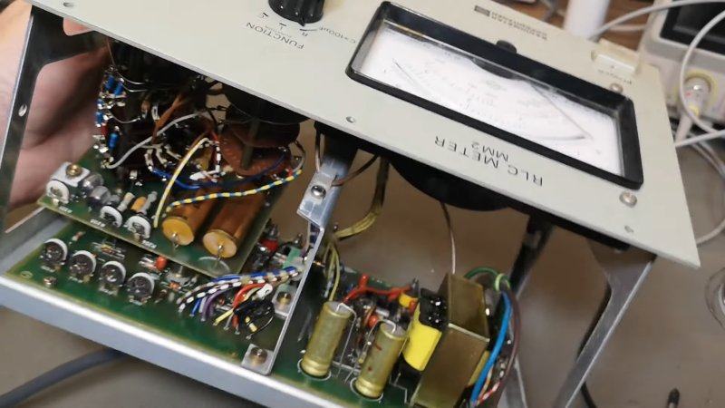
Modern test equipment is great, but there’s something about a big meter with a swinging needle and a mirror for parallax correction that makes a device look like real gear. [Thomas] shows us a Danish LCR meter (or, as it says on the front, an RLC meter). The device passes AC through the component and uses that to determine the value based on the setting of a range switch. It looks to be in great shape and passed some quick tests. Have a look at it in the video below.
An outward inspection shows few surprises, although there is an odd set of terminals on the back labeled DC bias. This allows you to provide a DC voltage in case you have a capacitor that behaves differently when the capacitor has a DC voltage across it.
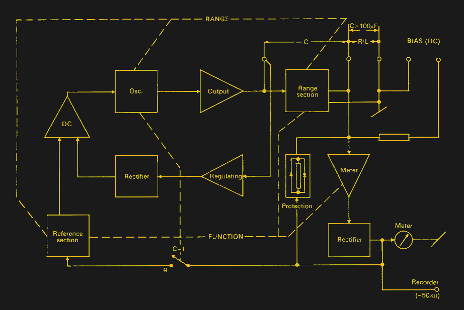
The circuit can measure — as the name implies — resistance, inductance, and capacitance. The manual shows a nice block diagram if you want to understand what’s going on.
Physically opening it up was a bit of a puzzle. That older gear was often well-constructed. Inside are some nice PCBs, a lot of transistors, and beautiful wiring harnesses. Someone took their time building this unit, and it shows.
Usually, when you see gear like this, it is a bridge, and you have to zero the meter, but not so with the MM2. These days, you are likely to use a microcontroller to measure the charge and discharge rate.


I have an AVO Model 7 meter from the early 1950s that has a “Capacity” setting as well as the usual V and R. But you have to supply your own 50 Hz AC at “62V to 250V”, ie probably UK mains! First you apply your voltage, adjust a knob for FSD, and then reapply with the capacitor under test in series. The manual warns not to touch the capacitor while testing and also to short the test leads after testing to discharge the meter! It also describes how to measure electrolytics in this way by pre-charging them with DC of the correct polarity and working quickly.
Page 18 http://www.richardsradios.co.uk/AVO/avo7instructions.pdf. I have not tried this particular setting on my AVO!
Why are DC bias terminals a surprise? Any decent LCR meter intended for banch use will allow for applying DC bias, and older gear usually used an exeternal source. My WW-II surplus unit has the same (I haven’t used it in many years, as it is 60Hz or 400Hz excitation only using the supplied AC as the source. No tubes–> no oscillator)
Which brings me to ask “Ask Hackaday” again.
For around 3 decades (3 deci-century) I have possessed (2) Impedance Meters,
of which I do not know how to use.
Here is what the labels say:
Bridge, Impedance Model 815AFA
NSN 6625-00-695-7669
Brown Electro-Measurement Corp
Seattle WA 88155
Contract No. F41606-08-D-0066
All I have found with web searching is a manual from BECO (probably the same company, but in Portland OR, and a different model) with different faceplate, controls, and connector and knob designations.
Does anyone know if National Stock Numbers (NSN) are in a database and would list an accompaniment manual?
Or know how to look up the Contract Number?
I do have one of those $15 LCR meters from China and it works OK for reading components, but these look too good to end up in a parts bin.
Probably could just open a similar manual like this (even has a theory section)
https://www.ietlabs.com/pdf/Manuals/GR/1656%2520Impedance%2520Bridge.pdf
And figure out what you need to know.
Ooops bad link… https://www.ietlabs.com/pdf/Manuals/GR/1656%20Impedance%20Bridge.pdf
Thank you!