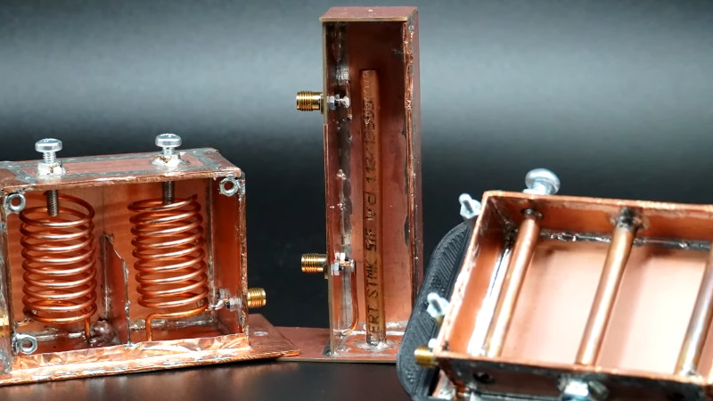
A tuned circuit formed by a capacitor and an inductor is a familiar enough circuit, and it’s understood that it will resonate at a particular frequency. As that frequency increases, so the size of the capacitor and inductor decrease, and there comes a point at which they can become the characteristic capacitance and inductance of a transmission line. These tuned circuits can be placed in an enclosure, at which they can be designed for an extremely high Q factor, a measure of quality, and thus a very narrow resonant point. They are frequently used as filters for that reason, and [Fesz] is here with a video explaining some of their operation and configurations.
Some of the mathematics behind RF design can be enough to faze any engineer, but he manages to steer a path away from that rabbit hole and explain cavity filters in a way that’s very accessible. We learn how to look at tuned circuits as transmission lines, and the properties of the various different coupling methods. Above all it reveals that making tuned cavities is within reach.
They’re a little rare these days, but there was a time when almost every TV set contained a set of these cavities which were ready-made for experimentation.


My first job out of college was at an aerospace waveguide manufacturer and I got to play with these kinds of filters for a few tests.
Absolute witchcraft.
Witchcraft indeed! VHF radios use racks of these when the antennas are in close proximity, tuning them can be quite a pain. Had to deal with one that was sensitive to vibration (walking past the rack would set the VSWR a-jiggling), basically involved dismantling, cleaning and retuning.
Inside was all silver plated and the entry and exit ‘ports’ of the cavity were nothing more than small antennas radiating into the cavity. Despite this lack of physical connection between in and out (there was around 3 feet of air between these antennas) the coupling between them was very good. 50W in and 49W out, how that works is black magic
I think using beer kegs as filter cavities for VHF is quite a clever idea: https://www.repeater-builder.com/antenna/pdf/beer-barel-cavity.pdf
There have even been commercial offerings built around kegs, however I can’t remember the company name and I turned up nothing on google, soyy about that.
Oh well, the PDF i linked contains references to the commercial filters I was thinking of.
It’s way too early in the day for me yet – I shall not type before waking up.
before the cantenna was the kegtenna
i faced a big problem within tx filter cavity, corrosion, when we opened all resonant piece’s where transformed to like a sand
Ahh, so it wasn’t sealed well enough. The magic stuff leaked out.
I was amazed at the 3-cavity filter I found in my old AMPS Nokia cellphone. It took up a large fraction of the volume of the phone.
A delicate thing made largely of foil, but still had itty-bitty tune screws in the tops of the cavities. My, how construction of phones has changed in 30 years.
At 34GHz (200Gbaud datarates) filter, transmission lines, etc is all FM
I considered one as a first filter for FM reception of a difficult to get station for our cable pickup. There was an article on using one for slope detection of FM broadcasts with a crystal diode only! Something to look forward to when AM dies and you want a foxhole radio. I looked at a ham article that used a brand new garbage can and its tight fitting lid. A piece of new stovepipe duct became the inside tower. Garbage can filters out all the garbage on a repeater.
FM reception (assuming on VHF broadcast band) would be hard at big distances due to different propagation and clogged spectrum. I would expect AM (again, assuming on MW frequencies) to last a lot more although the number of stations is way smaller, but building a AM transmitter on low HF frequencies would be much easier even using scrap parts in case of emergency.
Thanks for the explanation and finer details! Great tutorial! Here is a link to help with commercial product visuals: https://www.sinctech.com/pages/duplexers and to be fair: https://comprodcom.com/product-category/filters-rf-components/duplexers/ (there are many others too). For hams, coaxial (cavity) duplexers for 52MHz are approximately 6′ long (each one, and you need 4 minimum for a duplexer), are rare to obtain in the used/surplus market, and just as tricky to move or even locating them in the shack. Below 50 MHz, even commercial entities use helical resonators. At VHF (150 MHz), mobile (helical) duplexers don’t accommodate the required ham 600 kHz Tx/Rx repeater spacing, but are used for 5 MHz spacings, an example being the old VHF mobile phone band at 152/157 MHz. At UHF, Hams or GMRS enthusiasts, 5MHz Tx/Rx spacing comes together nicely to use a mobile duplexer for an inexpensive way to get a repeater up and running (in isolation away from any other transmitters).
A nice compromise between mobile and base station duplexers are the “Res-Lok” models that can be viewed in the web link above. Still… for shared antenna combining TX or RX below 470 MHz, full length cavity cans (or “scuba tanks”) are necessary to get down to 350 kHz spacing for required Q notch and bandpass characteristics. There are other aids that get into the closer frequency spacings… like circulators, isolators, hybrid combiners.
Keep in mind that what you can get away with for a “mobile” or stand-alone repeater lacks necessary characteristics to function at or near a shared tower site with protection from or to other tower users/frequencies. The follow-up topic becomes intermodulation (PIM) mitigation, which must be avoided.