One of the attractions of buying at the bottom end of the electronics market by mail order from China is that you never quite know what will come your way. Sometimes it’s a diamond in the rough, while with others it’s a mess. Occasionally along comes something which should work but doesn’t, and that’s the moment when you wonder if you could fix it. [Nyanpasu64] had just such a device, an HDMI to VGA converter with audio that didn’t work. What could be wrong?
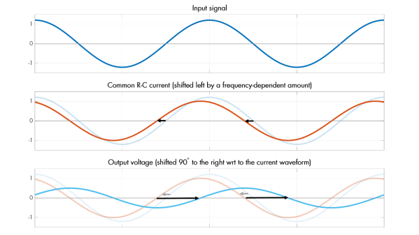
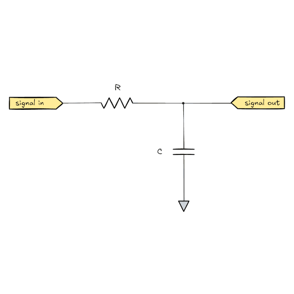
The HDMI to VGA chip has an onboard audio digital-to-analog converter (DAC), and it’s a delta-sigma design. This type of DAC is frequently used in audio applications because it works by shifting its switching frequency many times higher than the input sample rate, thus reducing considerably the distortion. This one wasn’t performing as advertised though, and the problem turned out to be that switching frequency being all over the output. Clearly the filter wasn’t working, which led to the design of a new filter. The write-up is therefore an extensive dive into filter design, and in part also a discovery of the effect of impedance on them.
For a super-cheap module to cause so much work, one might ask why not simply spend a few more dollars and get a better one. But had they done that we wouldn’t have seen this write-up, so we’re sticking with team cheap.
We’ve looked at audio DACs, in the past.