You’ve probably heard that a 3D printer is capable of producing its own replacement parts. Sometimes, that even includes upgraded or improved versions of the parts it was originally built with. But sometimes, it’s hard to figure out what improved really means. Think about air ducts that cool the part after printing. In theory, it should be easy to design a new duct. But how does it perform? Empirical testing can be difficult, but [Mike] shows how you can simulate the airflow so you can test design changes and validate assumptions before you print the actual part.
Of course, this wouldn’t only apply to printer ducts. You might also get some tips if you want to model airflow for PC cooling, hot air soldering, or other air-related projects. The free version of the software has some limitations, but it was surprisingly capable.
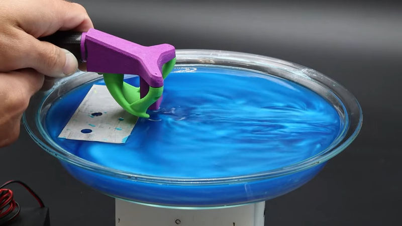
We also enjoyed how [Mike] used fluid to visualize the actual patterns and compared it to the simulation. The trick is using a compound from a kid’s science project kit, and it seems to work very well. Of course, you could just grab your smartphone. This might be worth thinking about if you are building a laser cutter air assist, too.


I’ve been trying to setup simulations with ElmerFEM for a week now. Electrostatic sims seem to work fine but I couldn’t get anything else to work.
Still its a brilliant tool with more options than I can understand