When it comes to building real-world flying vehicles, testing can be arduous and expensive. You have to find somewhere to fly, then you have to contend with environmental conditions and the possibility of damaging your craft if things go wrong. Simulation is a great solution to this, allowing testing without so much risk. To that end, [AlexanderRex] whipped up a platform for testing UAVs from the comfort of your computer desk.
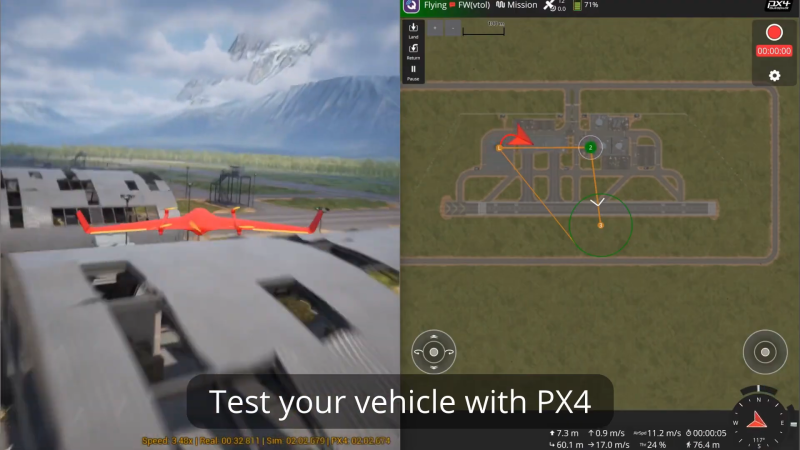
PteroSim is intended as a comprehensive test bench for simulating autonomous aerial vehicles. It can run PX4, ArduPilot, and Betaflight binaries right in the simulator. The autopilot code is given simulated sensor data, and in turn responds with actuator commands, just as it would in a real craft. The simulator runs the flight dynamics using JSBSim, and the resulting scene is rendered in Unreal Engine 5.
If you’ve ever wanted to quickly road test different autopilot settings without heading out to the field or risking hardware, this is a great way to do so. It’s hard to beat the speed of iteration that is possible when testing on the computer on your desk. We’ve featured similar work before, too.
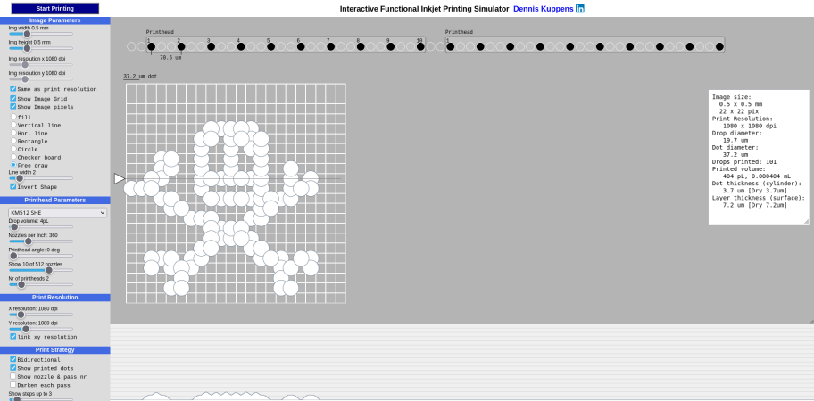
Love them or hate them, inkjets are still a very popular technology for putting text and images on paper, and with good reason. They work and are inexpensive, or would be, if not for the cartridge racket. There’s a bit of mystery about exactly what’s going on inside the humble inkjet that can be difficult to describe in words, though, which is why [Dennis Kuppens] recently released his Interactive Printing Simulator.
[Dennis] would likely object to that introduction, however, as the simulator targets functional inkjet printing, not graphical. Think traces of conductive ink, or light masks where even a single droplet out-of-place can lead to a non-functional result. If you’re just playing with this simulator to get an idea of what the different parameters are, and the effects of changing them, you might not care. There are some things you can get away with in graphics printing you really cannot with functional printing, however, so this simulator may seem a bit limited in its options to those coming from the artistic side of things.
You can edit parameters of the nozzle head manually, or select a number of industrial printers that come pre-configured. Likewise there are pre-prepared patterns, or you can try and draw the Jolly Wrencher as the author clearly failed to do. Then hit ‘start printing’ and watch the dots get laid down.
[Dennis] has released it under an AGPL-3.0 license, but notes that he doesn’t plan on developing the project further. If anyone else wants to run with this, they are apparently more than welcome to, and the license enables that.
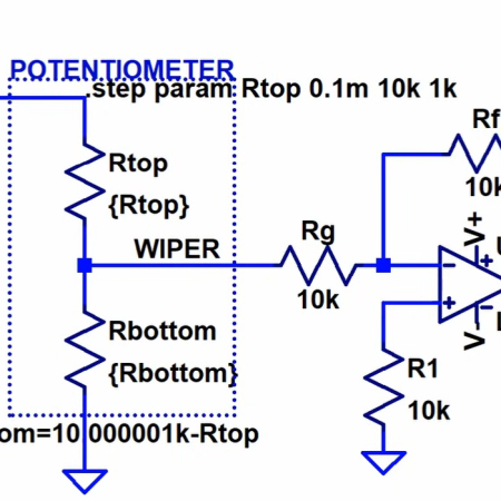
One of the good things about simulating circuits is that you can easily change component values trivially. In the real world, you might use a potentiometer or a pot to provide an adjustable value. However, as [Ralph] discovered, there’s no pot component in LTSpice. At first, he cobbled up a fake pot with two resistors, one representing the top terminal to the wiper, and the other one representing the wiper to the bottom terminal. Check it out in the video below.
At first, [Ralph] just set values for the two halves manually, making sure not to set either resistor to zero so as not to merge the nets. However, as you might guess, you can make the values parameters and then step them. Continue reading “Simulating Pots With LTSpice”→
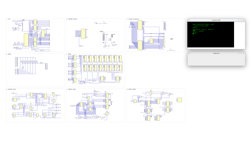
This project is serious business. The simulation environment used is Digital. Digital is a digital logic designer and circuit simulator designed for educational purposes. It’s a Java program that runs under the JVM. It deals in .dig files which are XML files that represent the details of the simulated hardware components. You don’t need to write the XML files by hand, there is a GUI for that. Continue reading “Simulating The Commodore PET”→
Procedural generation is a big part of game design these days. Usually you generate your map, and [Fractal Philosophy] has decided to go one step further: using a procedurally-generated world from an older video, he is procedurally generating history by simulating the rise and fall of empires on that map in a video embedded below.
Now, lacking a proper theory of Psychohistory, [Fractal Philosophy] has chosen to go with what he admits is the simplest model he could find, one centered on the concept of “solidarity” and based on the work of [Peter Turchin], a Russian-American thinker. “Solidarity” in the population holds the Empire together; external pressures increase it, and internal pressures decrease it. This leads to an obvious cellular automation type system (like Conway’s Game of Life), where cells are evaluated based on their nearest neighbors: the number of nearest neighbors in the empire goes into a function that gives the probability of increasing or decreasing the solidarity score each “turn”. (Probability, in order to preserve some randomness.) The “strength” of the Empire is given by the sum of the solidarity scores in every cell. Continue reading “Simulating Empires With Procedurally Generated History”→
LTSpice is a tool that every electronics nerd should have at least a basic knowledge of. Those of us who work professionally in the analog and power worlds rely heavily on the validity of our simulations. It’s one of the basic skills taught at college, and essential to truly understand how a circuit behaves. [Mano] has quite a collection of videos about the tool, and here is a great video explanation of how a bootstrap circuit works, enabling a high-side driver to work in the context of driving a simple buck converter. However, before understanding what a bootstrap is, we need to talk a little theory.
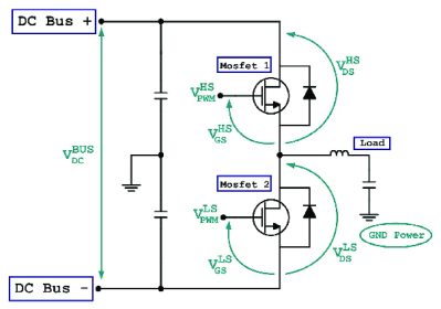
Bootstrap circuits are very common when NMOS (or NPN) devices are used on the high side of a switching circuit, such as a half-bridge (and by extension, a full bridge) used to drive a motor or pump current into a power supply.
A simple half-bridge driving illustrates the high-side NMOS driving problem.
From a simplistic viewpoint, due to the apparent symmetry, you’d want to have an NMOS device at the bottom and expect a PMOS device to be at the top. However, PMOS and PNP devices are weaker, rarer and more expensive than NMOS, which is all down to the device physics; simply put, the hole mobility in silicon and most other semiconductors is much lower than the electron mobility, which results in much less current. Hence, NMOS and NPN are predominant in power circuits.
As some will be aware, to drive a high-side switching transistor, such as an NPN bipolar or an NMOS device, the source end will not be at ground, but will be tied to the switching node, which for a power supply is the output voltage. You need a way to drive the gate voltage in excess of the source or emitter end by at least the threshold voltage. This is necessary to get the device to fully turn on, to give the lowest resistance, and to cause the least power dissipation. But how do you get from the logic-level PWM control waveform to what the gate needs to switch correctly?
The answer is to use a so-called bootstrap capacitor. The idea is simple enough: during one half of the driving waveform, the capacitor is charged to some fixed voltage with respect to ground, since one end of the capacitor will be grounded periodically. On the other half cycle, the previously grounded end, jumps up to the output voltage (the source end of the high side transistor) which boosts the other side of the capacitor in excess of the source (because it got charged already) providing a temporary high-voltage floating supply than can be used to drive the high-side gate, and reliably switch on the transistor. [Mano] explains it much better in a practical scenario in the video below, but now you get the why and how of the technique.
If you’ve ever fumbled through circuit simulation and ended up with a flatline instead of a sine wave, this video from [saisri] might just be the fix. In this walkthrough she demonstrates simulating a Colpitts oscillator using NI Multisim 14.3 – a deceptively simple analog circuit known for generating stable sine waves. Her video not only shows how to place and wire components, but it demonstrates why precision matters, even in virtual space.
You’ll notice the emphasis on wiring accuracy at multi-node junctions, something many tutorials skim over. [saisri] points out that a single misconnected node in Multisim can cause the circuit to output zilch. She guides viewers step-by-step, starting with component selection via the “Place > Components” dialog, through to running the simulation and interpreting the sine wave output on Channel A. The manual included at the end of the video is a neat bonus, bundling theory, waveform visuals, and circuit diagrams into one handy PDF.
If you’re into precision hacking, retro analogue joy, or just love watching a sine wave bloom onscreen, this is worth your time. You can watch the original video here.