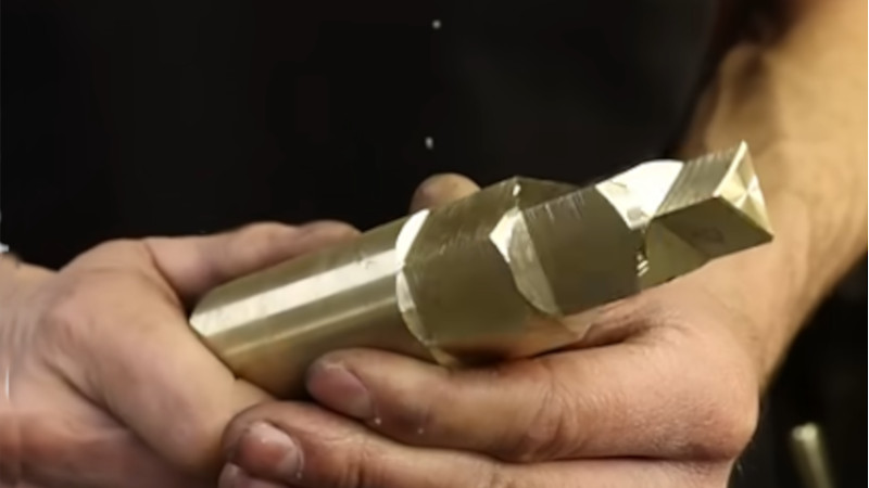
Most professionals would put a polygon on the end of a turned part using a milling machine. But many a hobbyist doesn’t have a mill. And if the polygon needs to be accurately centered, remounting the stock costs accuracy.
[Mehamozg] demonstrates you can turn a polygon on a lathe.
Polygons on shaft ends are surprisingly common, whether you are replacing a lost chuck key, need an angular index, or need a dismountable drive. As the video shows, you can definitely make them on the lathe.
But how the heck does this work? It seems like magic.
Lets start by imagining we disengage and lock the rotating cutter in [Mehamozg]’s setup and run the lathe. If the tool is pointed directly at the center we are just turning normally. If we angle the tool either side of center we still get a cylinder, but the radius increases by the sin of the angle.
Now, if we take a piece of stock with a flat on it and plot radius versus angle we get a flat line with a sin curve dip in it. So if we use [Mehamozg]s setup and run the cutter and chuck at the same speed, the cutter angle and the stock angle increase at the same time, and we end up with a flat on the part. If the cutter is rotating an even multiple of the chuck speed, we get a polygon.
The rub in all this is the cutter angle.. At first we were convinced it was varying enormously. But the surface at the contact point is not perpendicular to the radius from center to contact. So it cancels out, we think. But our brains are a bit fried by this one. Opinions in the comments welcomed.
We like this hack. It’s for a commonly needed operation, and versatile enough to be worth fiddling with the inevitable pain of doing it the first time. For a much more specialized machining hack, check out this tool that works much the same in the other axis.


Cool trick, but many a hobbyist’s lathe can’t do that turny tool trick either. My Chinesium lathe can’t, but I do also have a Chinesium mill.
Powered lead screws are pretty common even on smaller cheaper machines, and it’s fairly obvious from the video how he’s built this attachment so it would not be rocket surgery to add it to almost any lathe.
Using a car CV joint / driveshaft is pretty clever, high quality for low cost.
Sin curve…is that like a sin tax?
“but the radius increases by the sin of the angle.”
Sin does have a way of spinning out of control.
“Sin” should be sine. Please delete my comment after!
Mehamozg is a very good and modest guy :-). It is worth to see all of his videos even if you do not speak Russian. (by the way “Meha-mozg” = Mech-brain in Russian) He presents many useful tricks related to works on lathe.
This article really needs some more background then a youtube short. The same guy who made the short, has made a longer video. Looking at some other video’s I see at least one of the big boys (DMG MORI) makes tools for this, and I see 10+ year old video’s.
In the video below a guy is experimenting with some math, and the flatness of the sides, and it can be at least “fairly good”.
https://www.youtube.com/watch?v=CEQkOWgoYU8
I have not watched the whole video, for the occasions I want some polygons, milling seems to be more practical. This method seems more useful for mass production because of the specialized tools and the setup time.
That video does a good job of showing the paths cut out and demonstrating that there are multiple ways to achieve the same polygon, with some resulting in flatter sides than others. In fact, you can choose to have sides that are concave or convex, basically letting you make torx bits and other interesting shapes. He wrote a program and made a webpage to let you experiment and see all the possible outcomes: https://ridethegeartrain.com (scroll down to get to polygon cutting)
Btw, the paths cut are exactly like the paths traced out by a Spirograph. The only difference is the frame of reference. In a Spirograph, the “workpiece” (paper) is still while the “cutter” (pen) both rotates and moves around it; in the lathe it’s the opposite-ish. The workpiece is rotating, while the cutter’s center is held steady (it still rotates, though).
Interesting. I’d never seen that trick before which surprises me.
Relative to mounting a milling cutter to the spindle and using a milling vice, this is rather more work though. And won’t do Woodruff keys.
That’s using the lathe as a mill and thus wouldn’t be guaranteed concentric, as mentioned in the article.
This YouTube video shows the process for making an add-on to a lathe for cutting polygons:
https://youtu.be/oCFfvmREacA?si=mebtgw5aAQJqUz2C
Flipping amazing. My old Graziano is looking at me all scandalized right now.
What an excellent technique, like all the best ‘old machinist’ tricks, this is so obvious when you see it done, heck I could probably work out the maths and draw up a chart if I had the motivation and time but not a hope on earth would I have originated the idea independently.
Definitely a hack hahah.
That operation is going to be really hard on the tooling…. probably won’t work on metals harder than butter. The vibration alone, aside from chatter, is going to mess up all kinds of alignments.
Neat application of geometry, though.