Machining A Two-Stroke Engine Out Of Aluminium

Recently [Camden Bowen] took a swing at machining a two-stroke engine out of billet aluminium, following adventures in 3D printing such an engine, as well as building one out of parts largely sourced from a hardware store. The sketchiest part here is probably the use of only a basic mill and lathe, making the milling of certain shapes a definite OSHA violation.
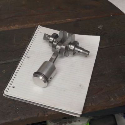
Two-stroke internal combustion engines are pretty simple from a mechanical point of view, with designs readily available. Add in a suitable material to machine and a modicum of machining and welding skills, and presto, you got yourself a not too shabby looking engine.

Of course, back in reality things are a bit more hairy. Not only are there many different ways to produce the parts – with some coming with a time penalty, monetary penalty, or both – but there are also myriad ways to hurt yourself and/or others. Fortunately [Camden] scraped by with just some (expensive) lessons learned and a major ruined part.

The final design features a single cylinder, with an initial pressure test showing a solid 150 PSI (10 bar) of compression. With that encouraging sign, a coil pack and contactor were added for some spark and a test run with the usual premixed gasoline-oil fuel.

Boringly, the engine mostly just runs and work as it should. This is of course not unexpected, much like how following the recipe for a pie produces said pie. But it does demonstrate how easy things are when you do not stray off the beaten path. The only significant issue was the flywheel wobbling slightly, likely due to a small manufacturing glitch, but this should not cause too many issues.

Continue reading “Machining A Two-Stroke Engine Out Of Aluminium”
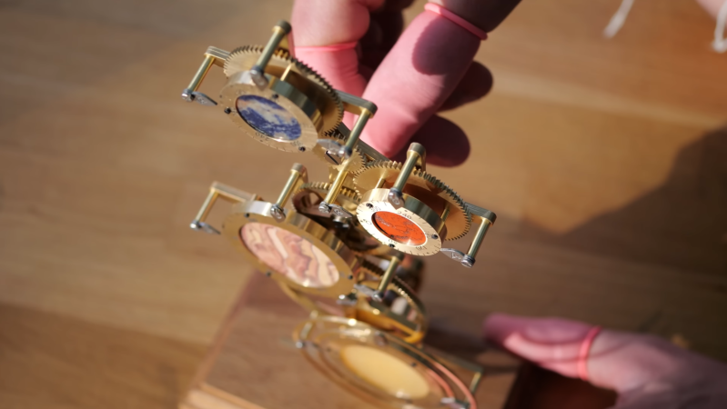
A brass and steel mechanism is shown, with a series of rotary dials on the front. Each dial is made out of a brass ring around the stone center. A man’s hand is behind the mechanism, turning a handle.

Interplanetary Clock Keeps Time Across The Solar System

There are some clocks, mostly in or around international airports, which have multiple faces to show the time at various cities around the world. Taking more a forward-looking approach is [Chronova Engineering], who built a clock to display the time on four different planets: Earth, Mars, Jupiter, and Saturn.

The clock doesn’t have any hands, but it uses rotating dials to represent a top-down view of each planet from it’s north pole. The dials have degree markings to represent rotation relative to each planet’s prime meridian; for the gas giants, rotation is measured by the rotation of the planet’s core. Each dial’s center is made out of a circular stone tile with patterns similar to those seen on the planet; Earth, for example, is represented with sodalite. Three pointers mounted around the dial indicate the longitudes which are currently experiencing sunrise, noon, and sunset. The mechanism can be turned with a handle or a knob, and a mechanical counter keeps track of the number of Earth days that have passed.

Continue reading “Interplanetary Clock Keeps Time Across The Solar System”

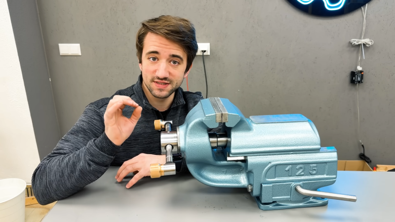
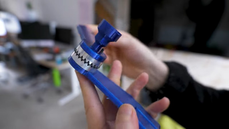
refurbished baby blue vice next to its refurbisher

Vice Of Old Brought To The Modern Age

People say they don’t make em’ like they used to, and while this isn’t always the case, it’s certainly true that old vices rarely die with time. This doesn’t mean they can’t use a refresh. [Marius Hornberger] recently backed that up when he decided to restore an old vice that had seen better days.

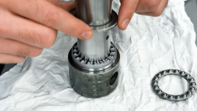
custom bearing and rod
Customized axial bearing assembly

When refreshing old tools, you’ll almost always start the same: cleaning up all the layers of grease and ruined paint. The stories that each layer could tell will never be known, but new ones will be made with the care put into it by [Marius]. Bearings for the tightening mechanism had become worn down past saving, requiring new replacements. However, simply swapping them with carbon copies would be no fun.

[Marius] decided to completely rethink the clamping mechanism, allowing for much smoother use. To do this was simple, just machine down new axial bearings, design and print a bearing cage, machine the main rod itself, and finally make a casing. It’s simple really, but he wasn’t done and decided to create a custom torque rod to hammer in his vicing abilities. Importantly, the final finish was done by spraying paint and applying new grease.

Old tools can often be given new life, and we are far from strangers to this concept at Hackaday. Make sure to check out some antique rotary tools from companies before Dremel!

Continue reading “Vice Of Old Brought To The Modern Age”

Clickspring’s Experimental Archaeology: Concentric Thin-Walled Tubing

It’s human nature to look at the technological achievements of the ancients — you know, anything before the 1990s — and marvel at how they were able to achieve precision results in such benighted times. How could anyone create a complicated mechanism without the aid of CNC machining and computer-aided design tools? Clearly, it was aliens.

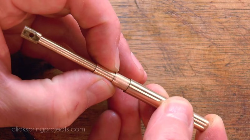
Or, as [Chris] from Click Spring demonstrates by creating precision nesting thin-wall tubing, it was human beings running the same wetware as what’s running between our ears but with a lot more patience and ingenuity. It’s part of his series of experiments into how the craftsmen of antiquity made complicated devices like the Antikythera mechanism with simple tools. He starts by cleaning up roughly wrought brass rods on his hand-powered lathe, followed by drilling and reaming to create three tubes with incremental precision bores. He then creates matching pistons for each tube, with an almost gas-tight enough fit right off the lathe.

Getting the piston fit to true gas-tight precision came next, by lapping with a jeweler’s rouge made from iron swarf recovered from the bench. Allowed to rust and ground to a paste using a mortar and pestle, the red iron oxide mixed with olive oil made a dandy fine abrasive, perfect for polishing the metal to a high gloss finish. Making the set of tubes concentric required truing up the bores on the lathe, starting with the inner-most tube and adding the next-largest tube once the outer diameter was lapped to spec.

Easy? Not by a long shot! It looks like a tedious job that we suspect was given to the apprentice while the master worked on more interesting chores. But clearly, it was possible to achieve precision challenging today’s most exacting needs with nothing but the simplest tools and plenty of skill. Continue reading “Clickspring’s Experimental Archaeology: Concentric Thin-Walled Tubing”

[Quinn Dunki] Makes A Screw Shortener Fit For Kings

It’s common problem when you’re building anything with screws: this one is too long, this one is too short. While she can’t teach you how to fix the latter, [Quinn Dunki] has made herself an absolutely deluxe screw shortening jig. And while that’s cool and all, the real value here is the journey; watching over [Quinn]’s shoulders while she’s in the machine shop is always illuminating.

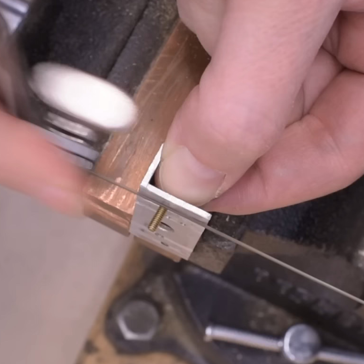
First off, she starts with her old jig, which frankly makes us want one. It’s a short piece of aluminum angle stock with threaded holes in it. You thread the screw in as far as you want, and use the edge as a cutting guide. Very nice!

But aluminum threads wear out quickly so it works if you’re shortening dozens of screws, but gets wonky when you need to cut hundreds. The new jig is made out of steel, and has a slit that clamps the threads in place so she doesn’t have to hold the tiny screws with her other hand while sawing.

This video is, on the surface, about making an improved tool out of steel. But it’s the tips along the way that make it worth your watch. For instance “deburr early and often” is a recurring leitmotif here: it keeps the extra bits that form along any cut from messing up edge finding or vise registration. And yeah, she deburrs after every operation.

There are mistakes, and lessons learned along the way. We’re not going to spoil it all. But in the end, it’s a sweet tool that we’ve never seen before.

If you haven’t read [Quinn]’s series on machine tools that she wrote for us, it’s a treasure trove of machining wisdom.

Continue reading “[Quinn Dunki] Makes A Screw Shortener Fit For Kings”

Lathe And Laser Team Up To Make Cutting Gear Teeth Easier

Fair warning: watching this hybrid manufacturing method for gear teeth may result in an uncontrollable urge to buy a fiber laser cutter. Hackaday isn’t responsible for any financial difficulties that may result.

With that out of the way, this is an interesting look into how traditional machining and desktop manufacturing methods can combine to make parts easier than either method alone. The part that [Paul] is trying to make is called a Hirth coupling, a term that you might not be familiar with (we weren’t) but you’ve likely seen and used. They’re essentially flat surfaces with gear teeth cut into them allowing the two halves of the coupling to nest together and lock firmly in a variety of relative radial positions. They’re commonly used on camera gear like tripods for adjustable control handles and tilt heads, in which case they’re called rosettes.

To make his rosettes, [Paul] started with a block of aluminum on the lathe, where the basic cylindrical shape of the coupling was created. At this point, forming the teeth in the face of each coupling half with traditional machining methods would have been tricky, either using a dividing head on a milling machine or letting a CNC mill have at it. Instead, he fixtured each half of the coupling to the bed of his 100 W fiber laser cutter to cut the teeth. The resulting teeth would probably not be suitable for power transmission; the surface finish was a bit rough, and the tooth gullet was a little too rounded. But for a rosette, this was perfectly acceptable, and probably a lot faster to produce than the alternative.

In case you’re curious as to what [Paul] needs these joints for, it’s a tablet stand for his exercise machine. Sound familiar? That’s because we recently covered his attempts to beef up 3D prints with a metal endoskeleton for the same project.

Continue reading “Lathe And Laser Team Up To Make Cutting Gear Teeth Easier”

Ball Nut Modification Charts A Middle Course Between Building And Buying

A lot of the projects we feature here on Hackaday engender the classic “build versus buy” argument. We’ve always been puzzled by that; if anyone can appreciate the sheer joy of making something rather than buying it, it should be our readers. But there’s something to be said for buying the stuff you can buy and concentrating your effort on the bespoke aspects of the project. It’s perhaps not as exciting, but needs must, oftentimes.

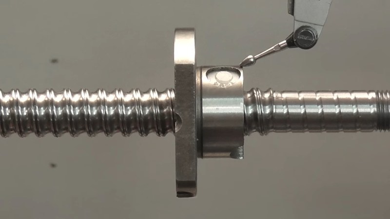
Let’s not forget there’s a third way though, which [Andy] explores with this ball nut modification project. Keen-eyed readers will recall [Andy]’s recent scratch-built ball screw build, in service of some top-secret, hush-hush project related to world domination and total subjugation of humanity. His homebrew efforts in this regard were a great lesson in how to machine a complex mechanism to work in a constrained space. Still, it left folks wondering why he’d go to all the trouble when he could have just trimmed an off-the-shelf part down to size. So, he decided to give that a try.

Continue reading “Ball Nut Modification Charts A Middle Course Between Building And Buying”