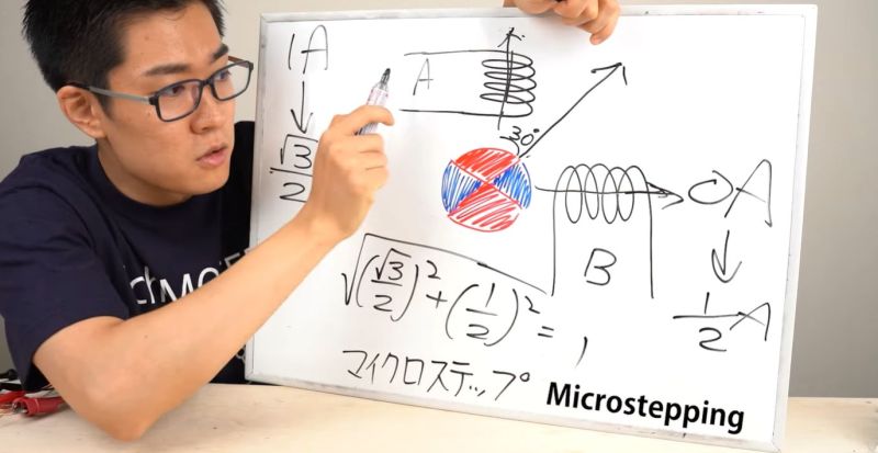
The [Denki Otaku] YouTube channel took a look recently at some stepper motors, or ‘stepping motors’ as they’re called in Japanese. Using a 2-phase stepper motor as an example, the stepper motor is taken apart and its components explained. Next a primer on the types and the ways of driving stepper motors is given, providing a decent overview of the basics at the hand of practical examples.
As great as theoretical explanations are, there’s a lot of value in watching the internals of a stepper motor move when its coils are activated in order. Also demonstrated are PWM-controlled stepper motor drivers before diving into the peculiarities of microstepping, whereby the driving of the coils is done such that the stator moves in the smallest possible increments, often through flux levels in these coils. This allows for significantly finer positioning of the output shaft than with wave stepping and similar methods that are highly dependent on the number of phases and coils.
As demonstrated in the video, another major benefit of microstepping is that it creates much smoother movement while moving, but also noted is that servo motors are often what you want instead. This is a topic which we addressed in our recent article on the workings of stepper motors, with particular focus on the 4-phase 28BYJ-48 stepper motor and the disadvantages of steppers versus servos.


Actually a very decent explanation
Yes, イチケン YT channel is a very high value knowledge source.
We used microsteppers for growing sapphire sheets and fiber at a very slow rate, sometimes as low as 1″ per hour. We were still getting more ripple than we liked so I did some tests. I mounted a first surface mirror at 45 degrees on the motor shaft and aimed a laser pointer at it. Watching the path across a distant ceiling, I could see speed variations. I decided that was caused by the motor coils not quite at 90 degees during construction. I had a driver that had adjustable offsets and that helped but every motor was a little different. Using precision gearboxes helped some but added its own small errors. We also used servos but they also used gearboxes with errors.
What was the final solution? Adding an encoder with finer precision that what you needed?
This was 30+ years ago. We decided a few more minutes in the Blanchard surface grinders that took the ripples out of the sapphire was good enough for things like supermarket scanner windows was good enough. I had plenty of other projects that had higher priority.
Slackstrap belt drive my man. We had to go back in time to find our solution lol. Oddly enough it undoes the overdoing of precision driving and the jitters. You will get slippage depending on the load it is moving, but we tried several gear configurations as mentioned above and kept having issues. Ymmv but once you get the tension right it is smooth grinding heh heh.
You should consider using ultrasonic motors for that application.
As shinsukke already mentioned, quite a nice write-up about the basic principles of hybrid stepper motors. One thing I do not agree with is the idea of “not very accurate”. Sure, they do have less resolution then industrial servo motors, and you can debate about what “very accurate” means. But they have good enough resolution for DIY metal working machines when combined with a 5mm pitch ballscrew, as is common these days. With a 5mm pitch and 200 steps/revolution, you get 25um per step, (close to 1/1000 banana unit) and with microstepping you can get that well below 10um. You can increase the resolution with microstepping some 4 to 32 times (so less than 1 um resolution with a 5mm pitch ballscrew) but then you’re getting into the manufacturing tolerances of the motors.
A follow up with more details would be nice. This can explain closed loop stepper motors, (Mentioned very briefly @12:41 “but some stepper motors have encoders apparently”. There is also an often completely misquoted very old (from the ’60-ies I think) statement that you would loose insane amounts of torque with very high microstepping rates. Another topic for a more detailed follow up are the ways in which the various trynamic motor controller IC’s improve motor efficiency and reduce noise.
Resonance of stepper motors is also a thing. When full stepping, the stepping “jolts” can stack up at certain frequencies (Combined with motor and shaft inertia) and make the whole thing unusable, but this is so much less with microstepping that it’s mostly a thing of the past.
If you commutate a stepper with an encoder-based feedback loop, it effectively is a servo motor but retains the benefits of a stepper motor. Good torque at high RPM plus good and stable holding torque at 0 RPM.
I’ve been using steppers in combination with M3 threaded rod and flexures in a similar way to OpenFlexure to produce a tiny 3D priner that moves in microns (latest http://blog.reprap.org/2025/02/maus-c-working-with-magnetic-slide-mount.html) and I’ve noticed that anything more than half-stepping is pretty notional position-wise. Things tend to not move amd then jump, and it’s not predictable. Microstepping certainly reduces vibration though, important when microns are involved!
It sound like your driving waveform is not well tuned. It will behave that non-linear way if the current is too high, for example. Measure your individual phase currents through all the microsteps through a full step: they should be (well) below the maximum allowed current, and should describe a sine wave pretty closely. The next level is to modify the sine wave to take out the residual nonlinearity.
I’d rather not know how they work and get on with my life and use them in all the wrong ways :P
In that case, just don’t read Hackaday.
joking! sheesh!